Analog Input and Output
Sensors like buttons produce only two states, which is convenient for the digital pins on the Teensy, but there are plenty of examples of sensors that produce voltages proportional to signals that cannot be read digitally. For example, the potentiometer can be wired to produce a voltage proportional to the angle of the knob. Microcontrollers, including the Teensy, have an analog to digital converter (ADC), to read the voltage and turn it into a digital number.
Visualizing Analog Voltages
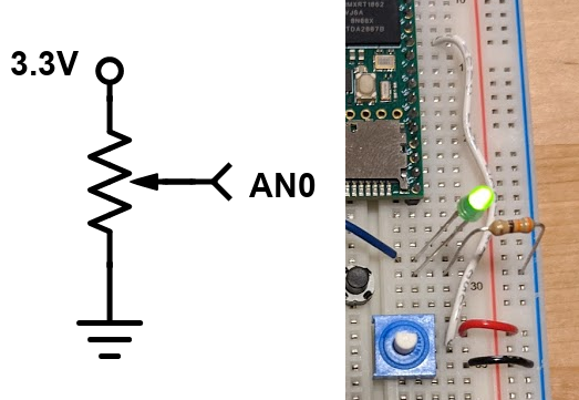
The potentiometer is a knob that can be used as an angle sensor, using the following circuit diagram:
 The pot circuit diagram
The potentiometer in the kit rotates 270 degrees, and the output voltage is linearly proportional to the angle (there are also logarithmic potentiometers, used as volume knobs). The output voltage can be read by any of the A pins on the Teensy, using the function analogRead(). The number returned by analogRead() is an integer from 0 (0V) to 1023 (3.3V).
Open the example AnalogReadSerial in 01.Basics. This example will read the voltage on pin A0, and then print the value to the computer using serial communication (we’ll explore serial in the next section). Load the code onto the Teensy, go to Tools->Port and select the option with Teensy 4.1, and open the Serial Monitor (button in the top right of the IDE, looks like a magnifying glass).
You should see a single column of text with a number from 0 to 1023 in the Serial Monitor. Turn the pot to verify that the number changes according to the angle. If the number does not change, check that the pot has 0V and 3.3V connected. Note that the number updates at 1kHz due to the 1ms delay in the code.
Slow the code down to 100Hz. This time, open the Serial Plotter in Tools. In this mode, if the data printed to the computer is columns of numbers separated by spaces, the data is plotted on a rolling graph that auto scales. The serial monitor and plotter are convenient ways to see the value of variables.
Note that every time you upload new code to the Teensy the port will briefly disappear. It is good practice to close the serial monitor or serial plotter before uploading new code, to prevent some random crashing of the Arduino IDE.
Set the brightness of the LED based on the potentiometer
Most microcontrollers don’t have the ability to generate analog voltages (using an internal digital to analog converter)((the Teensy does have a DAC, but we won’t use it for this purpose)). Instead, the microcontroller can digitally pulse a pin at high frequency so that the average value is an analog signal. The function that does this is called analogWrite(), and only certain pins are capable of outputting it (this functionality is more accurately called pulse width modulation, or PWM). analogWrite() takes a number from 0 to 255 for completely LOW to completely HIGH.
Edit the analogReadSerial code to apply the value read from A0 to the LED. Remember that analogRead() returns a maximum of 1023 and analogWrite() takes a maximum of 255, so do the math to divide the number down or funny things will happen. Load the code and watch the LED brightness level. Lots of other devices, like motors, can be driven like this, but usually need amplifiers because the microcontroller pin can only supply 3.3V and a few mA of current.
Build the phototransistor circuit
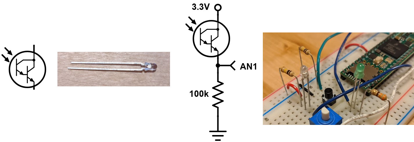
Another circuit that creates an analog voltage is a light level detector, using a phototransistor. A phototransistor is like a light controlled switch. When light hits the sensor, current flows through the phototransistor, so a resistor is used to turn the current into a voltage for the microcontroller to read. The phototransistor in your kit has a short leg that is more positive than the long leg, which is the opposite of the usual convention.
 The phototransistor circuit diagram
Build the circuit and edit the AnalogReadSerial code so that, in the serial plotter, the data fills across the plot in about 5 seconds by modifying the delay. Raise and lower your hand above the sensor and watch the plot.