Circuit Building
Some students might never have built a circuit before, and others might have a degree in it, so let’s start at the beginning. The first topic to cover is how to build a circuit out of electrical components and wire, using wire strippers and a breadboard.
How the breadboard works
A breadboard is a plastic housing for lots of conductive metal springs. By plugging conductors like wire and the metal legs of components into the springs, current can flow through the circuit, and voltages are applied to make the circuit operate.
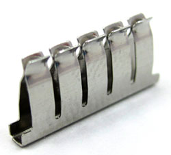 The spring clip inside the breadboard
 The breadboard and the arrangement of the clips inside
The matrix of holes are organized to assist in routing wires to different parts of the circuit. When a conductor touches another, they will have the same voltage. Often you want to share a voltage with several conductors, so the breadboard conductors are arranged to quickly expand access to a conductor by giving many access points via the holes.
The breadboard is three parts: two sides, and a larger center piece.
The center holes are connected as rows with 5 connected holes, and a break in the middle.
The sides of the breadboard, called the rails, are connected as long, uninterrupted columns.
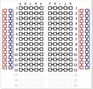 Breadboard internal layout
Each part of a circuit needs access to power and ground, so the rails are typically used to take the small number of power and ground pins from the source and give many access points to those voltages.
Cutting and stripping a wire
Circuits are built by connecting components together using conductor: wire! There are many types of wire, and with many sizes. The best wire for prototyping with a breadboard is 24 gauge, solid core insulated wire. The smaller the gauge, the thicker the wire and the more current it can supply without getting hot. Solid core wire is a single strand of wire that fits well into a breadboard. Stranded wire, usually 7 or 12 strands, is more flexible, the strands fray when getting plugged into a breadboard, so avoid using it for that purpose. Stranded wire is much better when you have a long distance to cover or need a flexible cable. The insulation prevents the wires from touching each other, and the color of the insulation should be used as a convention to remind you what the voltage or purpose of the wire is.
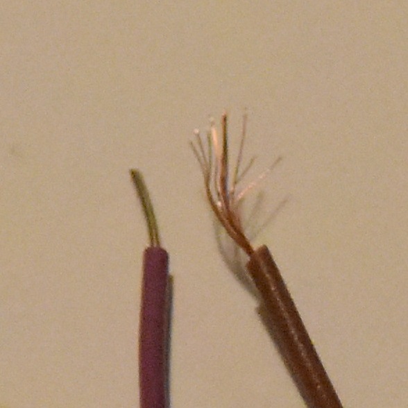 Solid and stranded wire
Prototyping wire is available as pre-cut and pre-bent kits, and as “male to male” wire. Your kit contains about 5 feet of 7 colors of wire, and a pair of wire strippers and cutters.
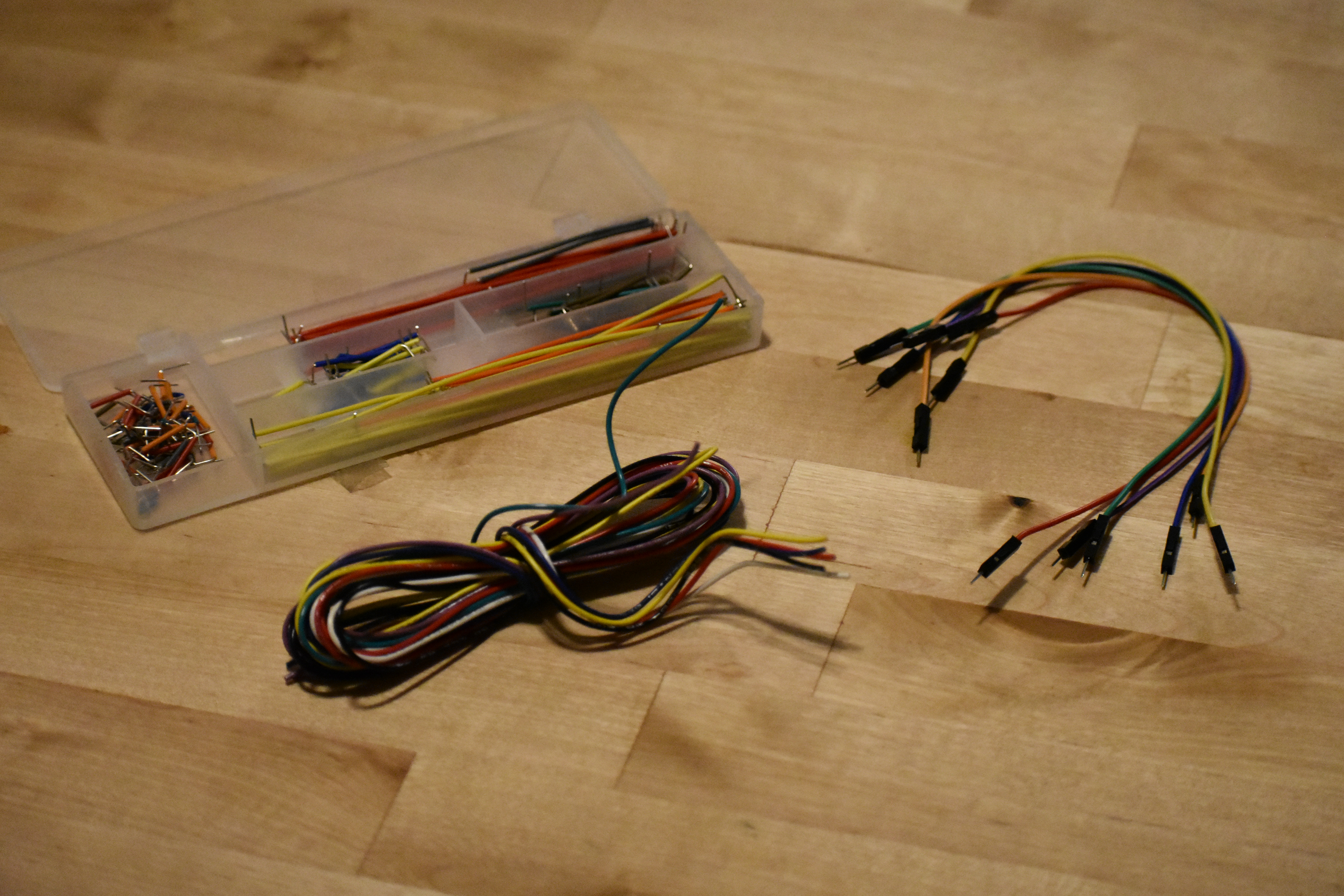 Wire kits
When you build a circuit, you should keep the wire color coded and in a “manhattan style”, or close to the board with 90 degree bends. The pre-cut and pre-bent wire kit is nice for keeping your circuit manhattan, but is hard to color code because each length of wire is a set color. The male to male headers are long, leaving long dangling wires that are easy to accidentally pull out. To stay true to our hands-on style, make each wire that you need, with the right color and length. This is slightly less convenient than the other types of wire, but the organization and reliability are well worth it.
For practice, make a 2 inch wire of each color. The base of the wire cutters is the cutter. Note that these cutters are only good for cutting wire, not other kinds of metal (they will get quickly destroyed if you try to cut a screw!) and don't use scissors to cut your wire, that will damage your scissors.
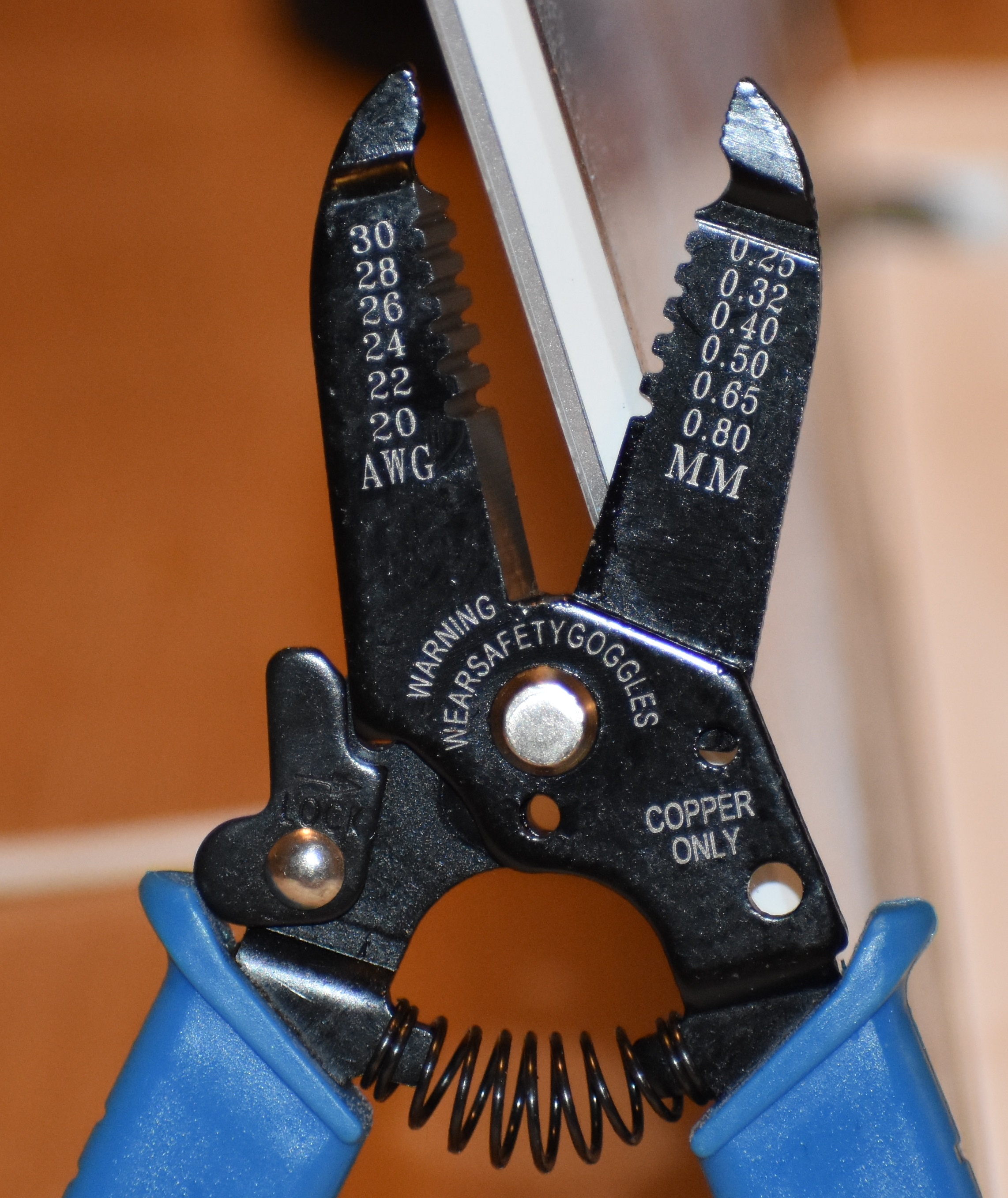 Wire cutters
After you cut the wire to length, use the appropriate hole to remove the insulation from each end, about ¼ inch. Use the alligator tooth hole to cut through the insulation, but not cut the wire. If you use a hole that is too big, the insulation will not get cut and won't be able to slide off. If you use a hole that is too small, the insulation will be cut through, but the wire will also be nicked, and that will eventually lead to the wire breaking at that point. Experiment a little and find the right size hole for your wire (this is experimentally because while the wire is 26 gauge, the wire strippers are inexpensive and your 26 size hole may be over or under ground, so you may need to use the 24 or 28.)
Use the Huzzah32 as a power supply and turn on an LED
Your breadboard already has some parts plugged in, including the Feather Huzzah32. Keep the Huzzah32 plugged in and remove the other parts for now. When removing large chips, be careful not to bend the pins as you remove the part. Lift a little from one side, then the other, until it comes out.
The Huzzah32 gets power from a USB cable, and we can use the Huzzah32 to power a circuit without any code. The Huzzah32 pinout is a map that describes what each pin is capable of doing. Use it to locate the 3.3V pin and ground pin.
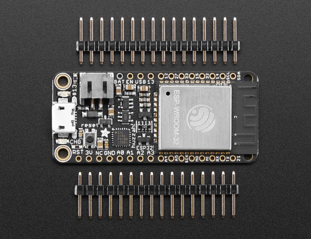 The Huzzah32 pinout
Do not plug the USB cable in while building your circuits, just in case you accidentally touch wires that have different voltages and create a short. A short can damage the component, the Huzzah32, or your computer! (It is actually hard to damage your computer, as long as you are not using an external power supply or battery with your circuit.)
The rows that these pins are plugged into provide 3.3V and 0V. We will need more than these holes, so connect these rows to the rails. The wire color convention is to use black wire for ground, and red wire for power. Wire is wire, so it will work the same for every color, but using this color convention will make it easier to identify bugs later on. Connect the rails from one side of the board to the other along the bottom of the board, so that you have lots of holes that provide 3.3V and 0V on both sides.
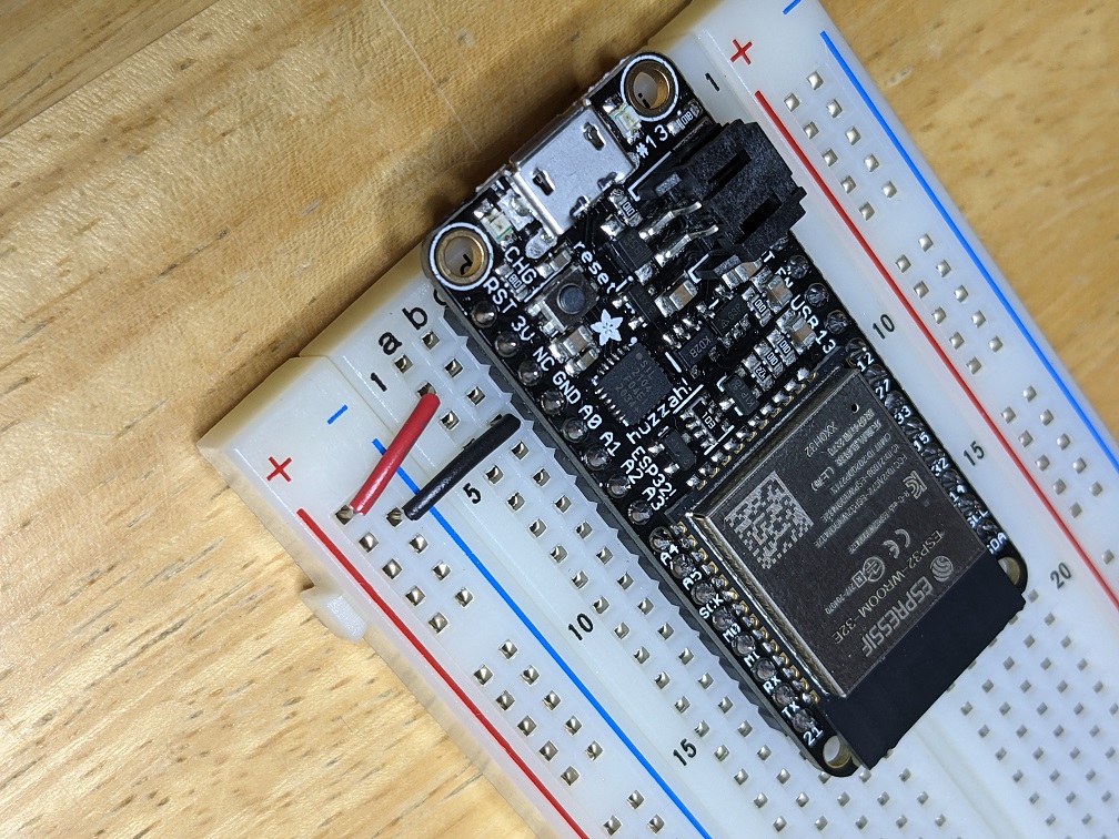 Power rails
Try to get the wires reasonably tight to the board. Big loopy wires are likely to catch on something, especially during transportation, and get pulled out.
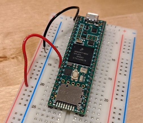 Bad wires
Current flows from higher voltage to lower voltage, so a circuit built from 3.3V to 0V will allow current to from 3.3V to 0V. A short is defined as an infinite current, which would happen if you connected 3.3V to 0V using a wire (don’t do that!). If the path the current takes passes through a resistor, the current is limited due to Ohm’s Law, V = IR. Current that passes through an LED will light up the LED. The first circuit to build is an LED with limited current.
The resistors in your kit have color bands to indicate their value. You have 330ohm (Orange Orange Brown Gold) and 100kOhm (Brown Black Yellow Gold).
Find a 330 ohm resistor and remove it from the strip.
Find a red LED, note that it has one long leg and one short leg, indicating that it is important which way it is plugged in (compared to the resistor, which can be plugged in either way).
 LED and resistor
The instructional map that shows your circuit is called a circuit diagram. Each component has a specific symbol.
The circuit diagram for the first circuit is 3.3V to the LED to the resistor to ground:
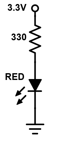 Power LED circuit diagram
Note that the long leg of the LED is the side that connects to the more positive voltage.
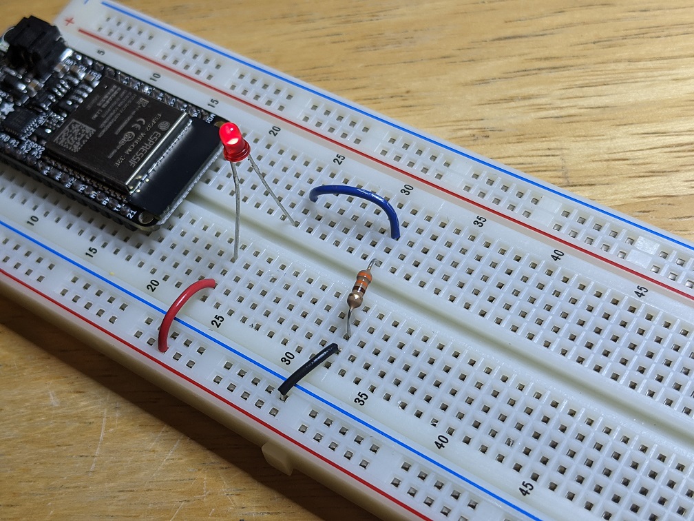
There are infinite ways to build this circuit on the breadboard. Each way will work just as well, it is all up to you! The diagram says that the long leg of the LED must touch 3.3V. The short end of the LED must touch the resistor, and the other leg of the resistor must touch ground. The touching points cannot touch other voltages. One way to build this circuit is to take a red wire from the 3.3V rail and place it in a row, place the long leg of the LED in that row and the short end in a different row. Then the resistor would go in that row to another empty row, and a black wire would connect that row to the ground rail.
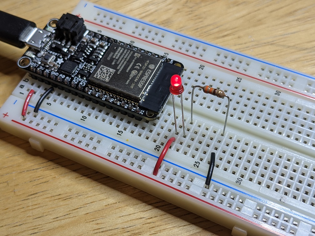 Power LED circuit
The legs of the LED and resistor are long, so you can trim them (keep the positive leg of the LED longer!) or bend them, in which case you might not need to use any wire!
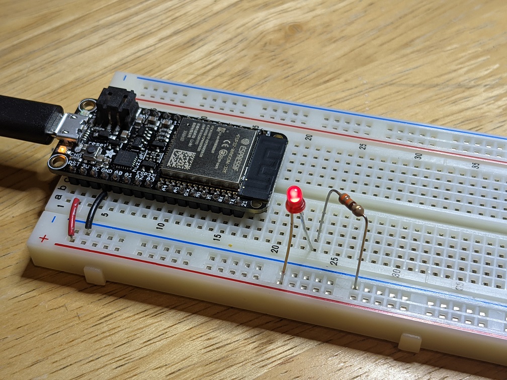 Power LED circuit
All of these circuits would work too:
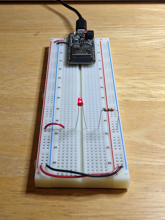 Power LED circuit
 Power LED circuit
Double check your work, then plug in the USB cable, and the LED should light. If it does not, check the orientation of the LED, all the connection points, and make sure there are no shorts.
Use a button to turn on LED
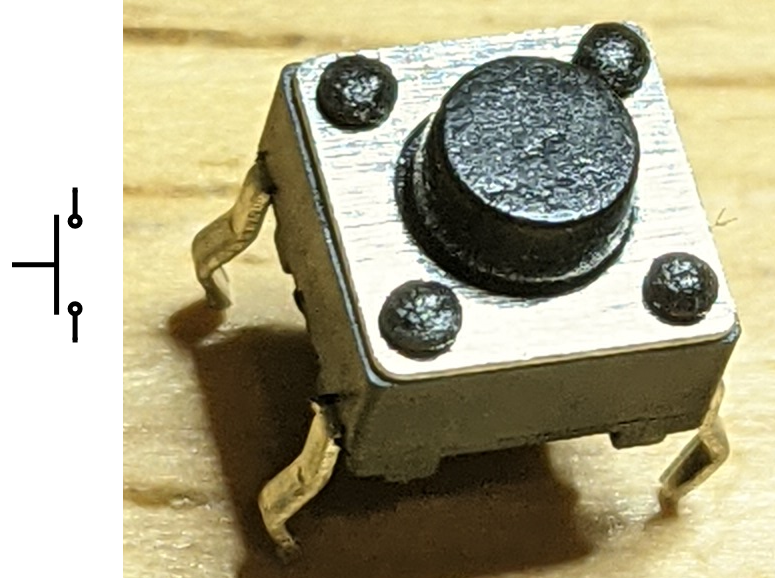
The push button in your kit is a spring loaded conductor that conducts when the button is pressed, and disconnects when it is not pressed.
 Pushbutton
This particular brand of button has four legs, even though electrically it only needs two. Four legs give it more mechanical stability, and the legs across the long side of the body are connected internally.
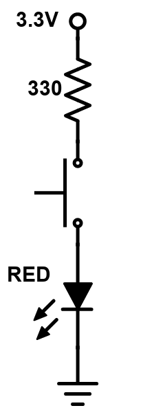
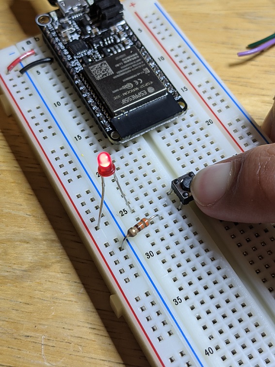
Build the following circuit with a green LED, 330ohm resistor, and push button:
 Pushbutton circuit diagram
 Pushbutton circuit
Press the button and the LED should light! If it doesn’t, carefully examine your circuit. Does it have connections to 3.3V and 0V? Does the long end of the LED touch the higher voltage? Are the connections made in the rows of the breadboard?
Use potentiometer to set LED brightness
The LED brightness is proportional to the current that goes through it. If we use a bigger resistor, the LED will be dimmer. If we use no resistor, the current would be extremely large and the LED might burn out! You can build a dimming LED by using a variable resistor, called a potentiometer (also just called a pot).
The pot has 3 legs:
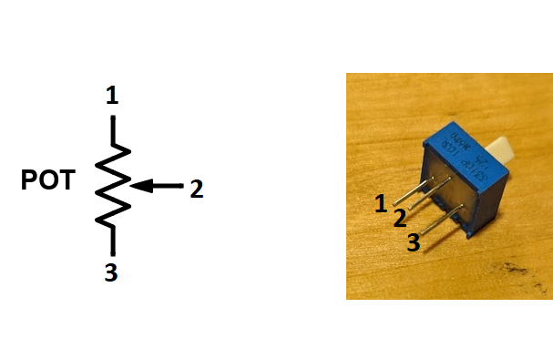 Potentiometer
In this case you only need 2 legs. Leave the third leg unconnected.
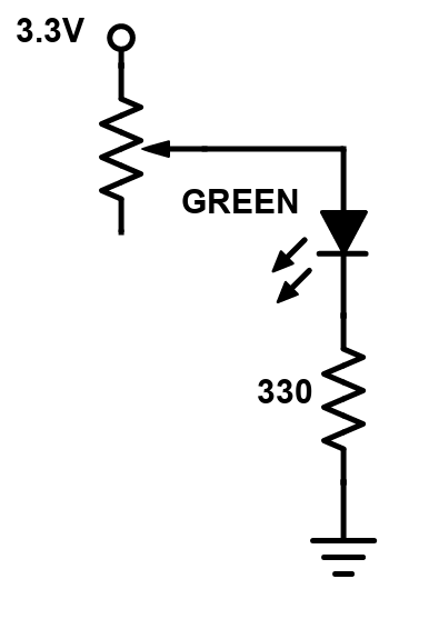 Potentiometer circuit diagram
The 330ohm resistor is used to make sure the LED has at least some resistance to prevent a short. This potentiometer has a value of 0ohm to 10kOhm, linearly proportional to the angle of the knob. Build the circuit (note that one leg of the pot is not used for anything), turn the knob, and the LED should dim!
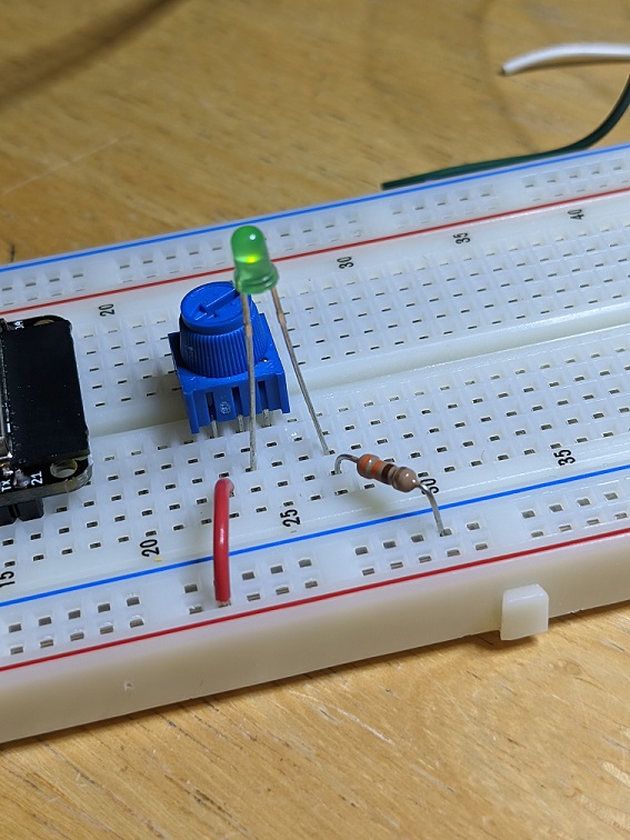 Potentiometer LED dimming circuit
Ok, that is enough raw circuit building for now. Let's move on to circuits controlled by code in the microcontroller.