EDI Mechatronics Boot Camp 2021
By Nick Marchuk
A manual for the mechatronics portion of boot camp, EDI 2021.
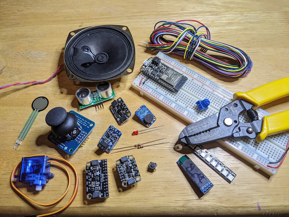
Before the Mechatronics Session
We will be using the ESP32 Feather Huzzah32, manufactured by Adafruit, and programmed with Arduino. You will need the mechatronics lab kit and a laptop with a USB A port (if you have only USB C you will need an adaptor).
Please install:
- The Arduino IDE (1.8.15) from https://www.arduino.cc/en/software
Instructions for getting the esp32 addon
Foreword
EDI Boot Camp is a great way to start the year. I always look forward to the creative projects and new faces.
Please make yourself comfortable in the Mechatronics Design Lab in Ford B100. It can get chilly in there so bring a sweatshirt!
If anything is missing, confusing, or flat out wrong, let me know.
Introduction to Mechatronics
Hands-on philosophy
Welcome to the Mechatronics portion of the EDI Bootcamp! This guide will introduce you to the parts in your lab kit, how to build circuits, Arduino programming, and the design process for electromechanical projects. You don’t need experience in any of these topics to get started! But you do need some desk space, a laptop, and some nimble fingers, because this is hands-on exploration and play time. Each section of this manual will guide you through a topic, show you one way to build a project, and then ask you to give it a try for yourself. Some solutions can be found at the end of the manual. It is important that you attempt to solve the exercises first, before jumping to the solution. The best way to use this material is to get your hands dirty, that’s where most of the learning happens!
How to get help
Whether you are in EDI Bootcamp or you happened upon this guide online, you are probably working on it individually, maybe even remotely. This is definitely not the ideal situation. A second set of hands and eyes, especially ones with experience, can make the difference between a fun and a frustrating project. Just remember that it is all part of the learning experience. In fact, the skill you will be practicing most is debugging. Usually debugging is associated with computer programming, but it can be applied to almost any task. Debugging is a “soft” skill, a process that must be experienced rather than taught. This manual will point out some techniques as it goes, but your best option is be methodical: document your work as you go, test as you build, and keep an open mind.
Bootcampers will be able to take advantage of office hours. Please come prepared with a sketch, circuit diagram, or your physical circuit.
Mechatronics and rapid prototyping
Mechatronics is the field of electromechanical design. It combines mechanical engineering of the physical design, electrical engineering of the sensors, drivers, and actuators, computer science of programming the code, and control theory for the design of the algorithms that lead from sensing to actuating.
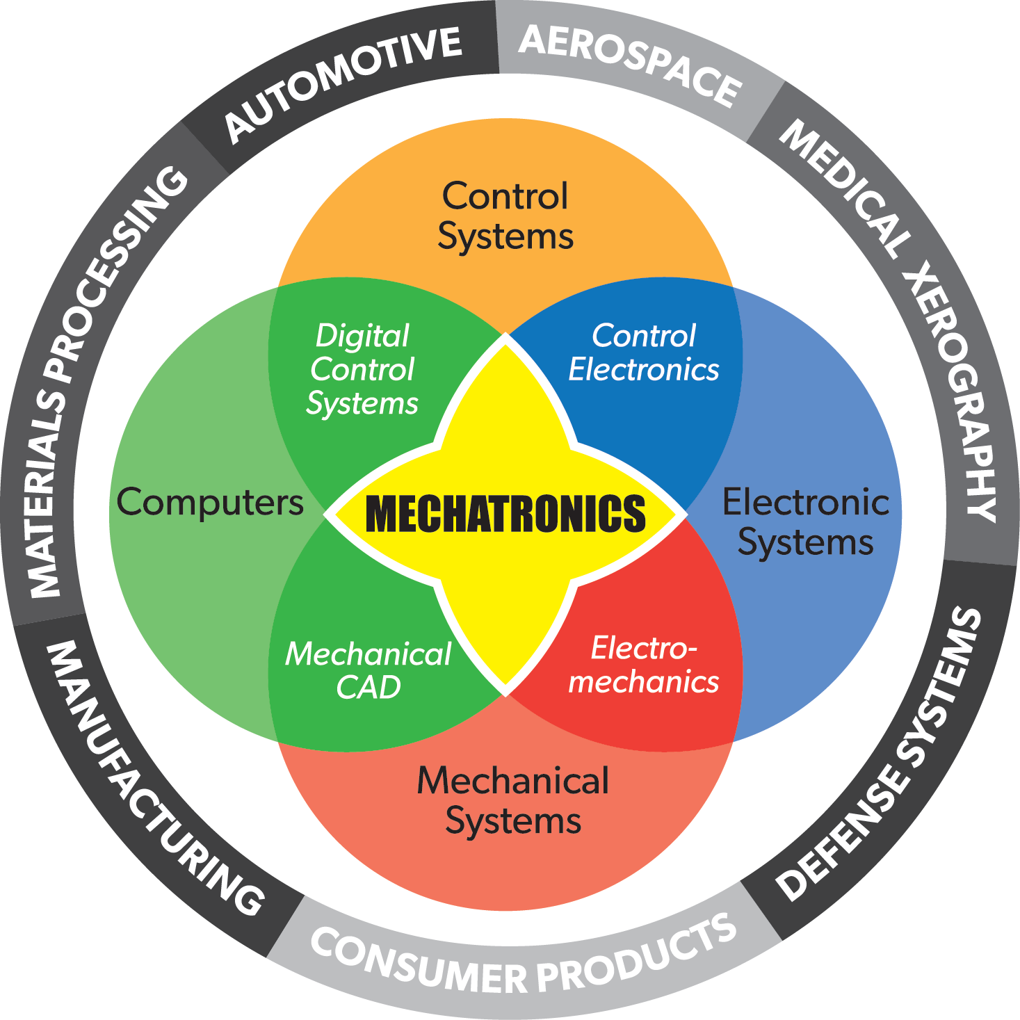 The Mechatronics venn diagram
You interact with mechatronic objects all the time. A microwave, a cell phone, and a car are all examples of mechatronic objects. Their design can be slick and smooth or chunky and obfuscated. They can also be tiny, expensive, and complicated, all of which point to objects that take lots of experts and time to design and build. But this is not necessarily the case. Hobbyist tools and open source software have reduced the barrier to entry to such low levels that mechatronics has become accessible to anyone with a laptop and the internet. Ideas that previously were left sketched out on the back of a napkin can now be whipped up with microcontroller dev kits and 3d printers in a matter of hours instead of weeks in a process referred to as rapid prototyping.
Arduino and ESP32
The tool that makes this all possible is Arduino. Before Arduino, electronic development tools were expensive and proprietary. The Arduino project, started at MIT, developed open source software and hardware that took advantage of the power of a laptop to allow everyone to write and compile code and place it on a low cost USB powered device. This spawned a DIY revolution that has created low cost 3d printers, inexpensive drones, and a dozen companies that cater to the community with an endless supply of cool sensors, LEDs, motors, and sample code.
“Arduino” is a loose term to describe the program where you write your code, a name for the electronic board that runs the code, and the code itself. But technically the program is an IDE, and there are several that you can choose to use, not just the official Arduino IDE. There are many brands of microcontroller boards that can be programmed using the IDE, not just official Arduin boards. And the code is technically C++, but don’t let that scare you away!
In this guide, we will use a microcontroller board from the company Espressif and assembeled onto a breakout board by Adafruit, called the Feather Huzzah32. This ESP32 is a modern 32bit ARM microcontroller running at 240MHz, with 4Mb program space and 520k SRAM, and can talk bluetooth and wifi, for about $18. Compare that to the classic Arduino Uno, with a 16MHz 8bit microcontroller, with 32k program space and 2k RAM, for about $30! The ESP32 runs the same code as the Uno and is also programmed using the Arduino IDE (using an add-on package), making it a super powerful electronics rapid prototyping board. There are lots of other microcontrollers available that use Arduino, some even run Python!
Other resources
The world of Arduino and accessible mechatronics would not exist without the dedicated DIY community behind it. You can find a list of our most commonly used suppliers and some great blogs in the Appendix.
Who am I and where to find me
This manual is written by Nick Marchuk, Senior Lecturer in Mechanical Engineering at the McCormick School of Engineering and Applied Science at Northwestern University in Evanston, IL. Nick runs the Mechatronics Design Lab in the Ford Building, right next to the Prototyping Shop. The Mechatronics Lab contains oscilloscopes, power supplies, multimeters, function generators, soldering irons, 3d printers, and parts like wire, buttons, LEDs, and ICs. The lab is open on weekdays from 9am-6pm, and available 24 hours with wildcard access. Nick’s office is in the back of the lab, and Nick is available for open office hours every day according to the schedule posted on the door. (Please check with Nick for updated lab and office hours during Covid).
Nick can be reached at nick.marchuk at u.northwestern.edu
Kit Parts List
- Feather Hazzah32
- Micro USB cable
- Breadboard
- Neopixel stick
- IMU
- 2.5W Audio amplifier
- Plug and Play speaker
- Green LED
- Red LED
- Potentiometer
- Push button
- Wire strippers
- Resistors (330ohm, 10kOhm)
- Solid core wire (7 colors)
- RC servo
- Speaker
- Ultrasonic distance sensor
- Proximity Light and Gesture sensor
- Mini PIR sensor
- Analog Joystick
- 3" Speaker
- Capacitive Touch sensor
- Microphone
- Force sensitive resistor
- Lithium ion battery
- OLED display
Circuit Building
Some students might never have built a circuit before, and others might have a degree in it, so let’s start at the beginning. The first topic to cover is how to build a circuit out of electrical components and wire, using wire strippers and a breadboard.
How the breadboard works
A breadboard is a plastic housing for lots of conductive metal springs. By plugging conductors like wire and the metal legs of components into the springs, current can flow through the circuit, and voltages are applied to make the circuit operate.
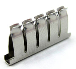 The spring clip inside the breadboard
 The breadboard and the arrangement of the clips inside
The matrix of holes are organized to assist in routing wires to different parts of the circuit. When a conductor touches another, they will have the same voltage. Often you want to share a voltage with several conductors, so the breadboard conductors are arranged to quickly expand access to a conductor by giving many access points via the holes.
The breadboard is three parts: two sides, and a larger center piece.
The center holes are connected as rows with 5 connected holes, and a break in the middle.
The sides of the breadboard, called the rails, are connected as long, uninterrupted columns.
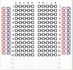 Breadboard internal layout
Each part of a circuit needs access to power and ground, so the rails are typically used to take the small number of power and ground pins from the source and give many access points to those voltages.
Cutting and stripping a wire
Circuits are built by connecting components together using conductor: wire! There are many types of wire, and with many sizes. The best wire for prototyping with a breadboard is 24 gauge, solid core insulated wire. The smaller the gauge, the thicker the wire and the more current it can supply without getting hot. Solid core wire is a single strand of wire that fits well into a breadboard. Stranded wire, usually 7 or 12 strands, is more flexible, the strands fray when getting plugged into a breadboard, so avoid using it for that purpose. Stranded wire is much better when you have a long distance to cover or need a flexible cable. The insulation prevents the wires from touching each other, and the color of the insulation should be used as a convention to remind you what the voltage or purpose of the wire is.
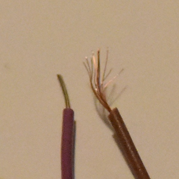 Solid and stranded wire
Prototyping wire is available as pre-cut and pre-bent kits, and as “male to male” wire. Your kit contains about 5 feet of 7 colors of wire, and a pair of wire strippers and cutters.
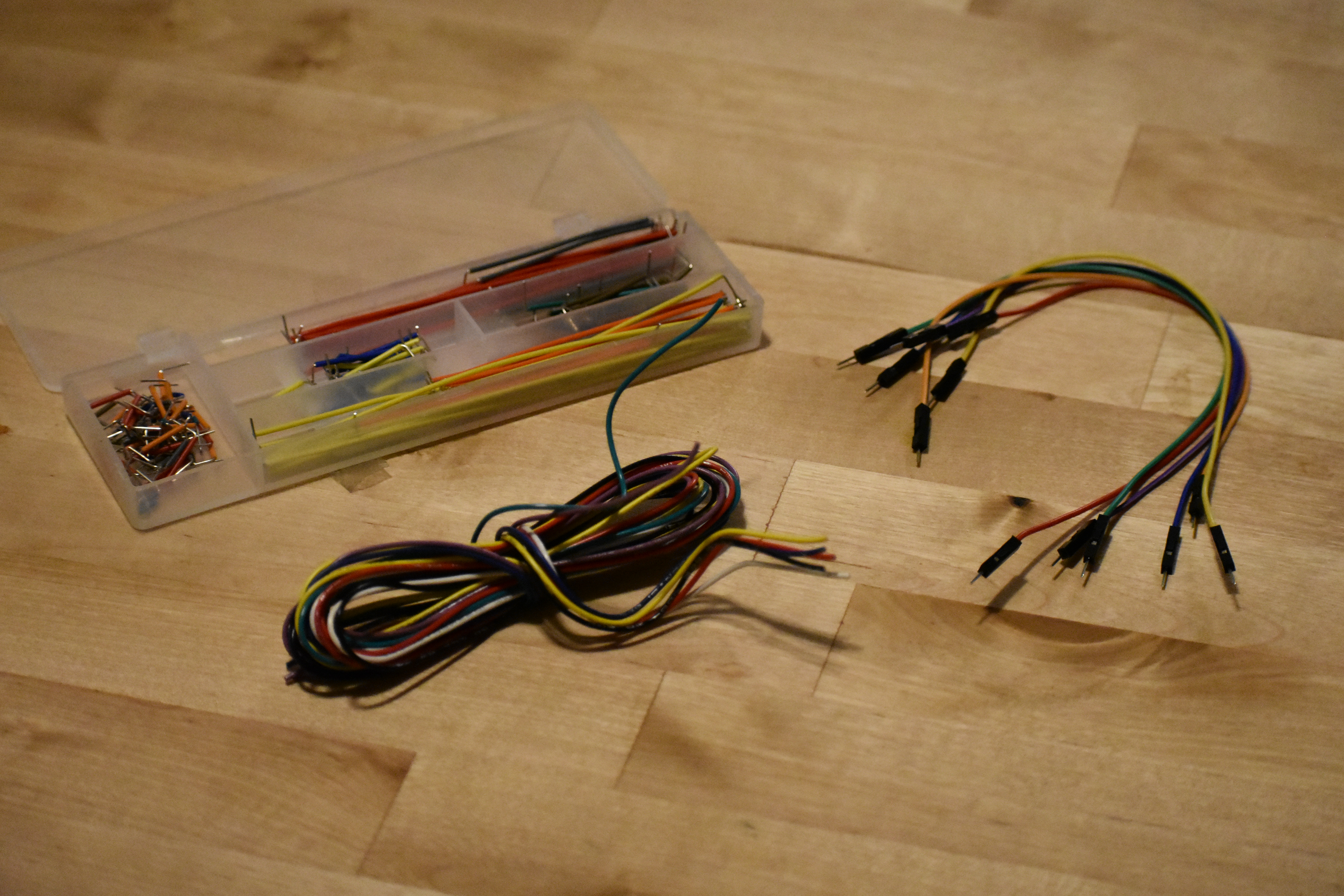 Wire kits
When you build a circuit, you should keep the wire color coded and in a “manhattan style”, or close to the board with 90 degree bends. The pre-cut and pre-bent wire kit is nice for keeping your circuit manhattan, but is hard to color code because each length of wire is a set color. The male to male headers are long, leaving long dangling wires that are easy to accidentally pull out. To stay true to our hands-on style, make each wire that you need, with the right color and length. This is slightly less convenient than the other types of wire, but the organization and reliability are well worth it.
For practice, make a 2 inch wire of each color. The base of the wire cutters is the cutter. Note that these cutters are only good for cutting wire, not other kinds of metal (they will get quickly destroyed if you try to cut a screw!) and don't use scissors to cut your wire, that will damage your scissors.
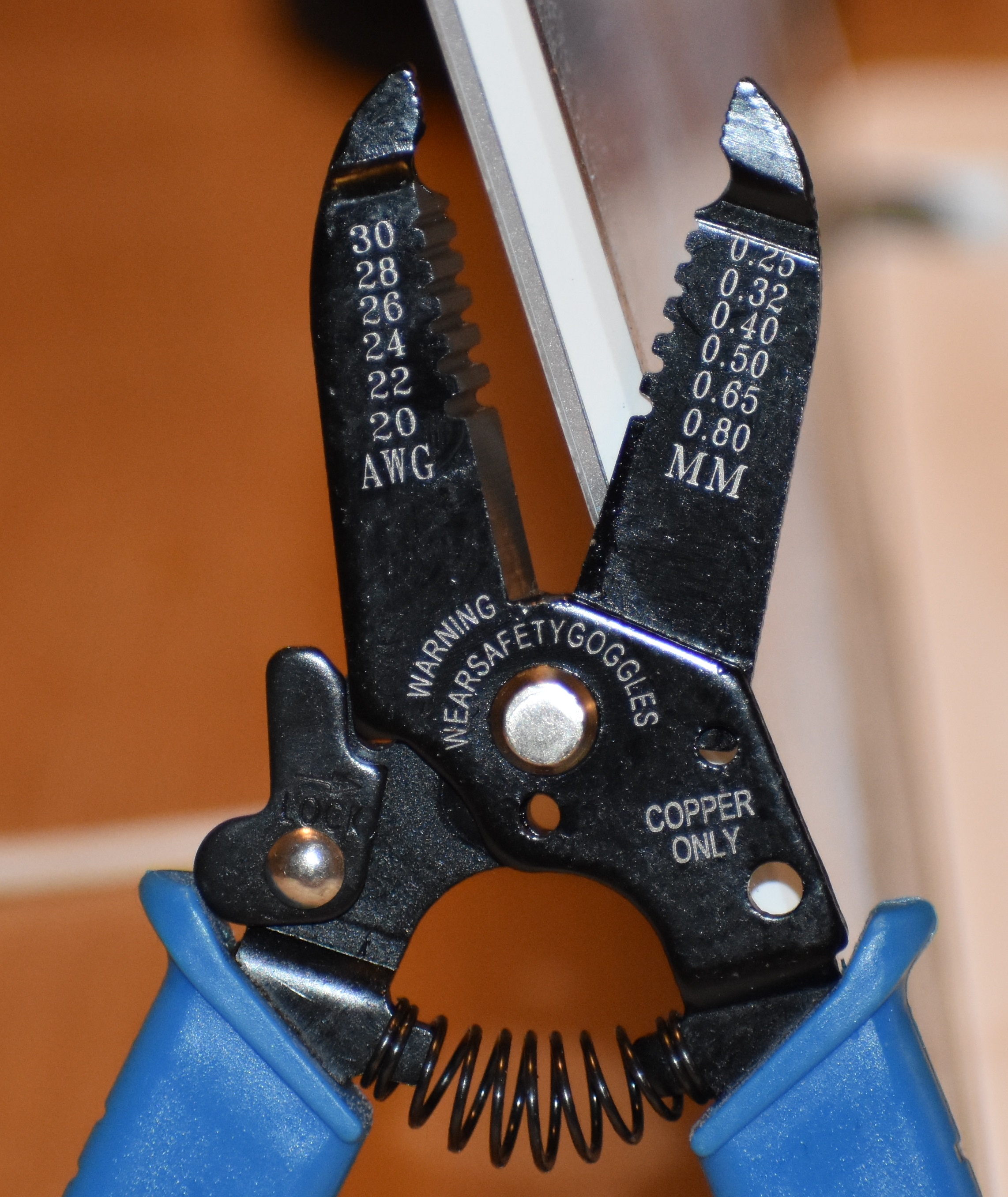 Wire cutters
After you cut the wire to length, use the appropriate hole to remove the insulation from each end, about ¼ inch. Use the alligator tooth hole to cut through the insulation, but not cut the wire. If you use a hole that is too big, the insulation will not get cut and won't be able to slide off. If you use a hole that is too small, the insulation will be cut through, but the wire will also be nicked, and that will eventually lead to the wire breaking at that point. Experiment a little and find the right size hole for your wire (this is experimentally because while the wire is 26 gauge, the wire strippers are inexpensive and your 26 size hole may be over or under ground, so you may need to use the 24 or 28.)
Use the Huzzah32 as a power supply and turn on an LED
Your breadboard already has some parts plugged in, including the Feather Huzzah32. Keep the Huzzah32 plugged in and remove the other parts for now. When removing large chips, be careful not to bend the pins as you remove the part. Lift a little from one side, then the other, until it comes out.
The Huzzah32 gets power from a USB cable, and we can use the Huzzah32 to power a circuit without any code. The Huzzah32 pinout is a map that describes what each pin is capable of doing. Use it to locate the 3.3V pin and ground pin.
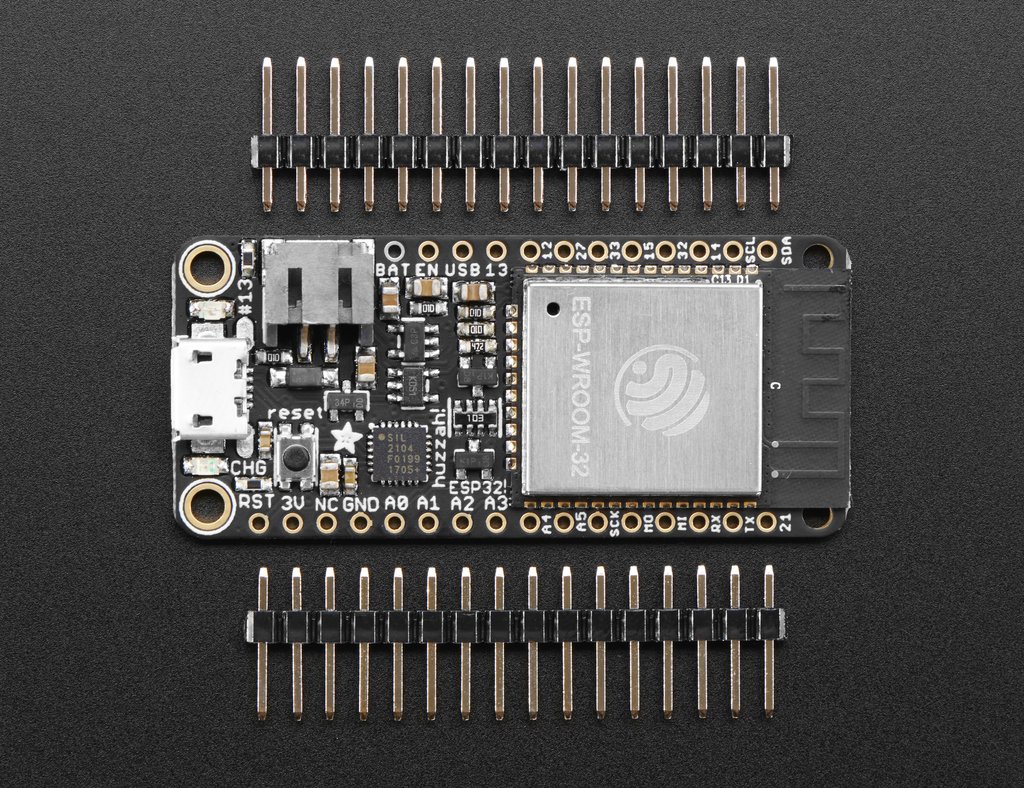 The Huzzah32 pinout
Do not plug the USB cable in while building your circuits, just in case you accidentally touch wires that have different voltages and create a short. A short can damage the component, the Huzzah32, or your computer! (It is actually hard to damage your computer, as long as you are not using an external power supply or battery with your circuit.)
The rows that these pins are plugged into provide 3.3V and 0V. We will need more than these holes, so connect these rows to the rails. The wire color convention is to use black wire for ground, and red wire for power. Wire is wire, so it will work the same for every color, but using this color convention will make it easier to identify bugs later on. Connect the rails from one side of the board to the other along the bottom of the board, so that you have lots of holes that provide 3.3V and 0V on both sides.
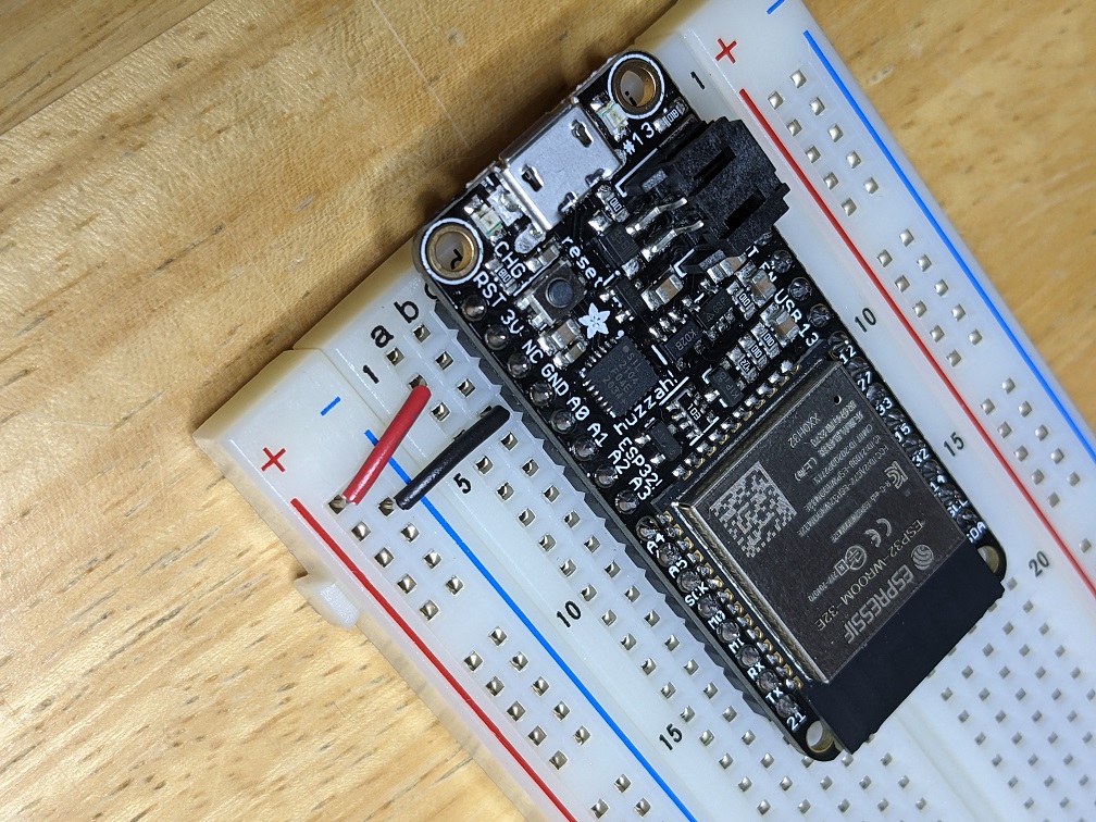 Power rails
Try to get the wires reasonably tight to the board. Big loopy wires are likely to catch on something, especially during transportation, and get pulled out.
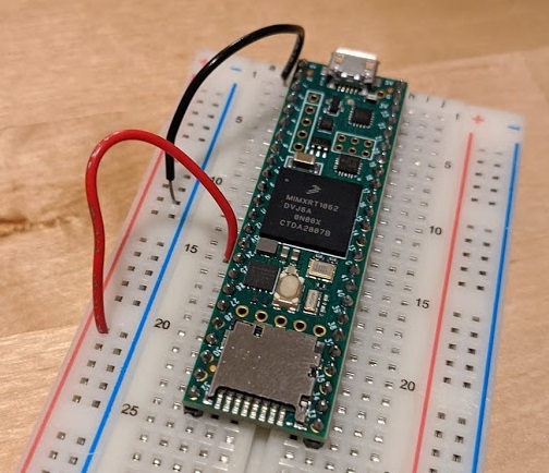 Bad wires
Current flows from higher voltage to lower voltage, so a circuit built from 3.3V to 0V will allow current to from 3.3V to 0V. A short is defined as an infinite current, which would happen if you connected 3.3V to 0V using a wire (don’t do that!). If the path the current takes passes through a resistor, the current is limited due to Ohm’s Law, V = IR. Current that passes through an LED will light up the LED. The first circuit to build is an LED with limited current.
The resistors in your kit have color bands to indicate their value. You have 330ohm (Orange Orange Brown Gold) and 100kOhm (Brown Black Yellow Gold).
Find a 330 ohm resistor and remove it from the strip.
Find a red LED, note that it has one long leg and one short leg, indicating that it is important which way it is plugged in (compared to the resistor, which can be plugged in either way).
 LED and resistor
The instructional map that shows your circuit is called a circuit diagram. Each component has a specific symbol.
The circuit diagram for the first circuit is 3.3V to the LED to the resistor to ground:
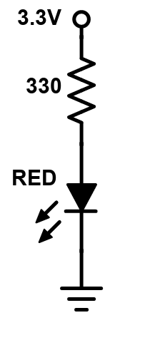 Power LED circuit diagram
Note that the long leg of the LED is the side that connects to the more positive voltage.
There are infinite ways to build this circuit on the breadboard. Each way will work just as well, it is all up to you! The diagram says that the long leg of the LED must touch 3.3V. The short end of the LED must touch the resistor, and the other leg of the resistor must touch ground. The touching points cannot touch other voltages. One way to build this circuit is to take a red wire from the 3.3V rail and place it in a row, place the long leg of the LED in that row and the short end in a different row. Then the resistor would go in that row to another empty row, and a black wire would connect that row to the ground rail.
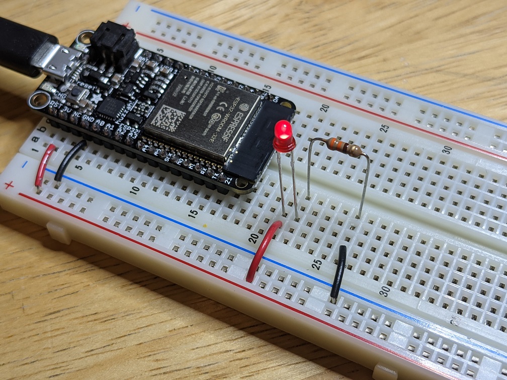 Power LED circuit
The legs of the LED and resistor are long, so you can trim them (keep the positive leg of the LED longer!) or bend them, in which case you might not need to use any wire!
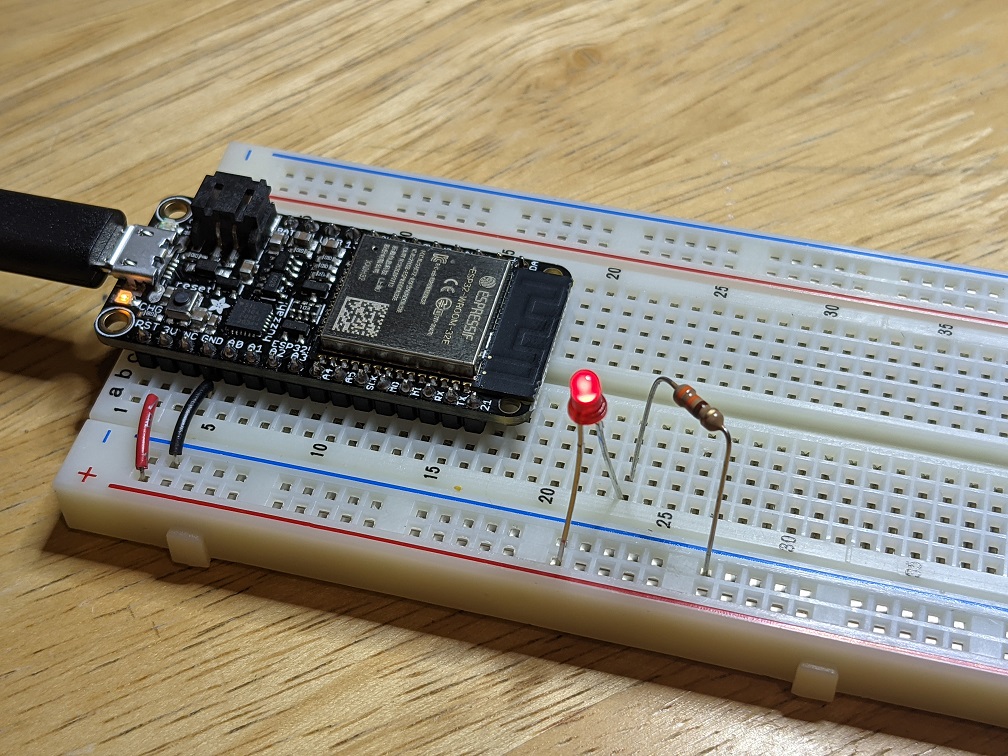 Power LED circuit
All of these circuits would work too:
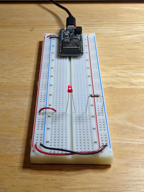 Power LED circuit
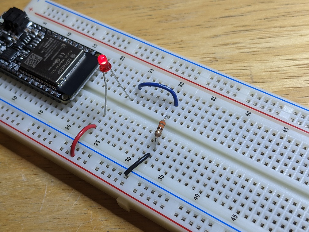 Power LED circuit
Double check your work, then plug in the USB cable, and the LED should light. If it does not, check the orientation of the LED, all the connection points, and make sure there are no shorts.
Use a button to turn on LED
The push button in your kit is a spring loaded conductor that conducts when the button is pressed, and disconnects when it is not pressed.
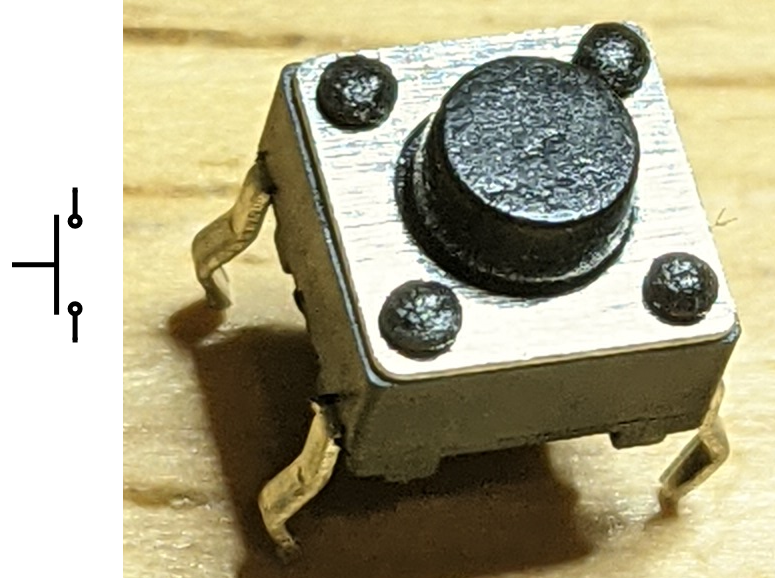 Pushbutton
This particular brand of button has four legs, even though electrically it only needs two. Four legs give it more mechanical stability, and the legs across the long side of the body are connected internally.
Build the following circuit with a green LED, 330ohm resistor, and push button:
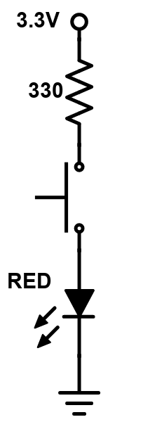 Pushbutton circuit diagram
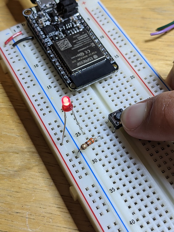 Pushbutton circuit
Press the button and the LED should light! If it doesn’t, carefully examine your circuit. Does it have connections to 3.3V and 0V? Does the long end of the LED touch the higher voltage? Are the connections made in the rows of the breadboard?
Use potentiometer to set LED brightness
The LED brightness is proportional to the current that goes through it. If we use a bigger resistor, the LED will be dimmer. If we use no resistor, the current would be extremely large and the LED might burn out! You can build a dimming LED by using a variable resistor, called a potentiometer (also just called a pot).
The pot has 3 legs:
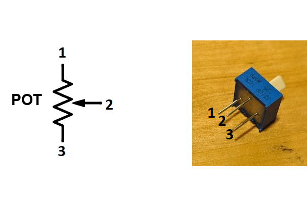 Potentiometer
In this case you only need 2 legs. Leave the third leg unconnected.
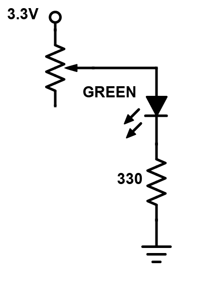 Potentiometer circuit diagram
The 330ohm resistor is used to make sure the LED has at least some resistance to prevent a short. This potentiometer has a value of 0ohm to 10kOhm, linearly proportional to the angle of the knob. Build the circuit (note that one leg of the pot is not used for anything), turn the knob, and the LED should dim!
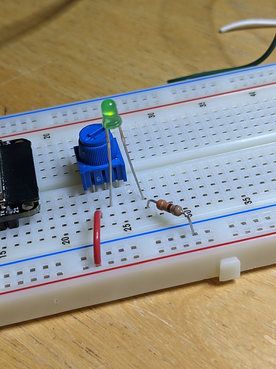 Potentiometer LED dimming circuit
Ok, that is enough raw circuit building for now. Let's move on to circuits controlled by code in the microcontroller.
Arduino code on the Huzzah32
We can build circuits all day long, using sensors like the potentiometer to control outputs like the brightness of an LED, but changing the functionality of the circuit often takes a lot of redesign and building. Instead, we can use code on a microcontroller, wired to simple circuits, to accomplish our objectives, and make it easy to change the functionality on the fly and prototype rapidly.
Installations
To program the Huzzah32, download and install version 1.8.15 of the Arduino IDE. Then, install the ESP32 addon in Tools->Board->Board Manager by searching for ESP32. (Full instructions).
Now that the software is installed, select the Adafruit ESP32 Feather from Tools->Board->ESP32 Arduino->Adafruit ESP32 Feather. (The default selection is Arduino Uno, if you leave this selection then the code will not be able to upload to the board).
Next, plug the Huzzah32 into your computer using the USB cable. To communicate with the board, you need to select the name of the communication port associated with this board in Tools->Port (look at Tools->Port with the board plugged in and not plugged in and select the name of the port that disappears when the board is not plugged in). You may need to install a driver from Silabs.
Open and run Blink
With the Arduino IDE open, the Adafruit ESP32 Feather board and port selected, go to File->Examples->0.1Basics->Blink. This sample code will blink an LED that is pre-soldered onto the Huzzah32. Press the Compile and Upload button (looks like a rightward facing arrow), and the Arduino will compile the code and load it onto the Huzzah32. When the code is loaded, a small red LED to the right of the USB port on the Huzzah32 should blink. (Note the first time you compile a sketch it will be agonizingly slow, because every file is being built from scratch. After the first time only code that changes will be compiled, so the process will be much faster).
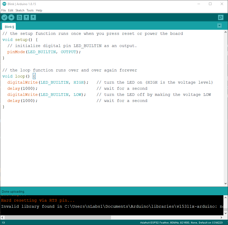 The Arduino IDE
Change Blink to be a different speed
Arduino code can be broken up into three sections:
- definitions
- setup()
- loop()
The definitions area is where you define variables, functions, and include libraries. setup() is a function that runs first, and is used to initialize variables and functions. loop() runs after setup(), and iterates over and over as long as the Huzzah32 has power. Let’s examine Blink.ino. The definition area contains comments, which are non-code text you can add to remind yourself what a variable or function is meant to do, and a variable called led that stores the number of the pin that is soldered to the orange LED. setup() initializes pin 13 to be an OUTPUT, which means that it can output 3.3V (HIGH) or 0V (LOW). By default, all pins are INPUT, which means they can read their voltage to know if they are HIGH or LOW, so if you want to use a pin as OUTPUT, you need to change it in setup(). loop() sets the voltage of pin 13 to HIGH, then waits 1000ms, then sets the voltage to LOW, then waits 1000ms. This makes the LED blink every 2 seconds.
Edit the code so that the LED blinks 10 times per second. How long should each delay be? Upload the code and verify that you can change the blinking rate. If you continue to increase the blinking rate, at what rate can you no longer tell that the LED is blinking, it just looks like it is always on?
Buttons and LEDs
Make a new file, copy in the contents of Blink, and save the file. Edit the code so that the Huzzah32 can read a button and control an LED. When the button is pressed, the LED should be on, and when the button is not pressed, the LED should be off. Here is the circuit diagram for the LED and button, using pins 3 and 4.
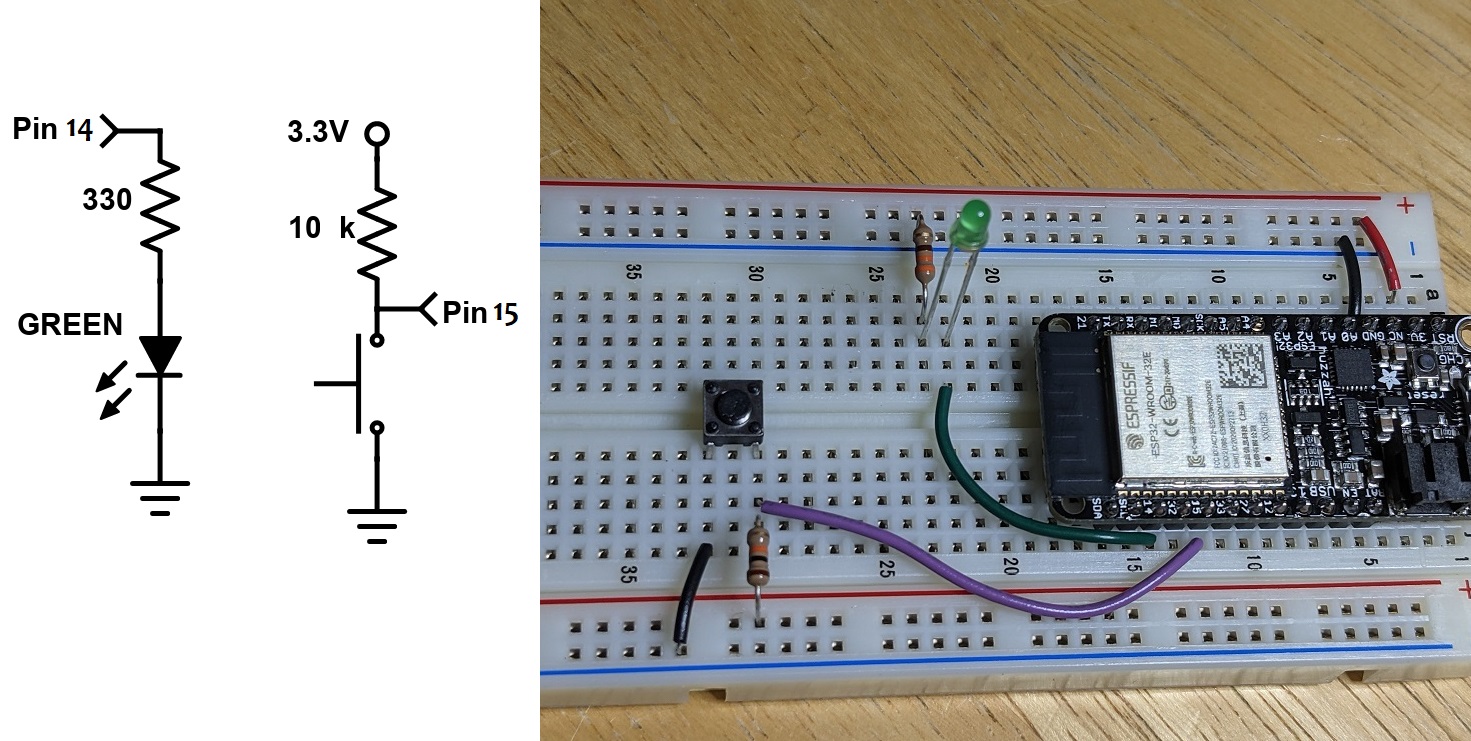 The Huzzah32 button and LED circuit diagram
Note that the button circuit is a little weird. What voltage does the Huzzah32 read when the button is pressed? When the button is not pressed?
Build an LED circuit, turn on when button is pressed
In the definitions part of your code, write a comment to remind yourself what this code will do. In setup(), set pin 3 to OUTPUT and pin 4 to INPUT. In loop(), use an if() statement with digitalRead() and digitalWrite() to control the LED based on the button.
Looking for help with the syntax? The Arduino reference page has help on every function and control structure: https://www.arduino.cc/reference/en/
Example: how to use if(): https://www.arduino.cc/reference/en/language/structure/control-structure/if/
Toggle the LED
Make another new file and copy in the previous code. Edit it to make the LED toggle every time the button is pressed (so if the LED is ON and the button is pressed, the LED should turn OFF and stay OFF until the button is released and pressed again). There are many ways to do this, but one way is to use a variable to remember if the LED is supposed to be on or off, and change the variable each time the button is pressed and released. You also need to know when the button was pressed, not just if the button is pressed, so you’ll need another variable to remember what the previous state of the button was.
Define the two variables in the definition area of the code. Call one int led_state = 0, and the other int but_prev = 1. In loop(), make a variable to save the current state of the button, int but_state = digitalRead(). In an if() statement if the but_state is LOW and but_prev is HIGH, change led_state to 1 if it is 0 or change led_state to 0 if it is 1. In a separate if() statement, turn the LED on if led_state is 1 or off if led_state is 0.
This method of writing code, checking the state of sensors one at a time, is called polling. The more states you have, the slower the overall performance of the code, because all of the states need to be checked. The Huzzah32 runs at 240MHz, so in general, you don’t have to worry about missing events. In fact, putting a small delay at the end of loop() might make things more reliable.
Use an interrupt to turn on the LED
Sometimes you can take advantage of a microcontroller ability called Interrupts. Interrupts are functions that are automatically called when an event occurs, and you don’t have to use polling style code to detect the event. Once you set up the interrupt, the function happens automatically! The pins on the Huzzah32 can be told to generate an interrupt on a FALLING edge using attachInterrupt() in setup(). Then write a function like void but_pressed() and it will automatically be called when the voltage on the pin goes from HIGH to LOW. Make a new file and recreate the toggle capability using an interrupt.
Analog Input and Output
Sensors like buttons produce only two states, which is convenient for the digital pins on the Huzzah32, but there are plenty of examples of sensors that produce voltages proportional to signals that cannot be read digitally. For example, the potentiometer can be wired to produce a voltage proportional to the angle of the knob. Microcontrollers, including the Huzzah32, have an analog to digital converter (ADC), to read the voltage and turn it into a digital number.
Visualizing Analog Voltages
The potentiometer is a knob that can be used as an angle sensor, using the following circuit diagram:
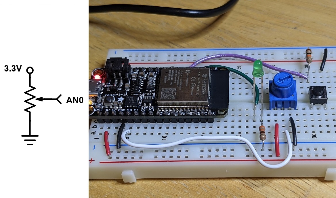 The pot circuit diagram
The potentiometer in the kit rotates 270 degrees, and the output voltage is linearly proportional to the angle (there are also logarithmic potentiometers, used as volume knobs). The output voltage can be read by any of the A pins on the Huzzah32, using the function analogRead(). The number returned by analogRead() is an integer from 0 for 0V to 4095 for 3.3V (this is a 12bit ADC).
Open the example AnalogReadSerial in 01.Basics. This example will read the voltage on pin A0, and then print the value to the computer using serial communication (we’ll explore serial in the next section). Load the code onto the Huzzah32, go to Tools->Port and select the option with Huzzah32, and open the Serial Monitor (button in the top right of the IDE, looks like a magnifying glass).
You should see a single column of text with a number from 0 to 4095 in the Serial Monitor. Turn the pot to verify that the number changes according to the angle. If the number does not change when you move the pot, check that the pot has 0V and 3.3V connected. Note that the number printing to the computer updates at 1kHz due to the 1ms delay in the code.
Edit the code to slow the output down to 100Hz. This time, open the Serial Plotter in the Tools menu. In this mode, if the data printed to the computer is columns of numbers separated by spaces, the data is plotted on a rolling graph that auto scales. Note the noise level on the voltage when the pot value is constant, this is electrical noise in the circuit and ADC, and there are some techniques for reducing it with circuits or code if it becomes an issue. The Serial Monitor and Plotter are convenient ways to see the value of sensor data and variables.
Note that every time you upload new code to the Huzzah32 the port will briefly disappear. It is good practice to close the Serial Monitor or Plotter before uploading new code, to prevent some random crashing of the Arduino IDE.
Set the brightness of the LED based on the potentiometer
Most microcontrollers don’t have the ability to generate analog voltages, using an internal digital to analog converter (the Huzzah32 does have a DAC, but we won’t use it for this purpose). Instead, the microcontroller can digitally pulse a pin at high frequency while varying the ratio of on to off time so that the average value is an analog signal. On most Arduino, the function that does this is called analogWrite(), which is a horrible name because the output voltage isn't actually analog, it is square, and only certain pins are capable of outputting it (this functionality is more accurately called pulse width modulation, or PWM). The Huzzah32 uses a different function, slightly more complicated, and also with a name that isnt quite right, but does give more options. First, in setup(), a channel is made for the PWM with a channel number, frequency, and resolution, using ledcSetup(ledChannel, freq, resolution), where the ledCannel can be 0, the freq 5000 (Hz), and the resolution 8 (bits, so values of 0-255). Second, in setup(), initialize the pin you want to use, using ledcAttachPin(ledPin, ledChannel), where ledPin is the number of the pin and channel can be 0. Then, in loop(), whenever you want to set the duty cycle of the PWM, use ledcWrite(ledChannel, dutyCycle), where ledChannel is 0 and dutyCycle is 0-255, 0 for 0V and 255 for 3.3V.
Edit the analogReadSerial code to apply the value read from A0 to the LED. Remember that analogRead() returns a maximum of 4095 and ledcWrite() takes a maximum of 255, so do the math to divide the number down or funny things will happen. Load the code and watch the LED brightness level. Lots of other devices, like motors, can be driven like this, but usually need amplifiers because the microcontroller pin can only supply 3.3V and a few mA of current.
Build the microphone circuit
Another circuit that creates an analog voltage is a microphone. The microphone in the kit is an electret type, and comes on a breakout board with an amplifier that conditions the signal so that the mean voltage is 1.65V and the magnitude changes with sound level. The breakout board has a tiny potentiometer built in so you can increase or decrease the gain to change the sensitivity.
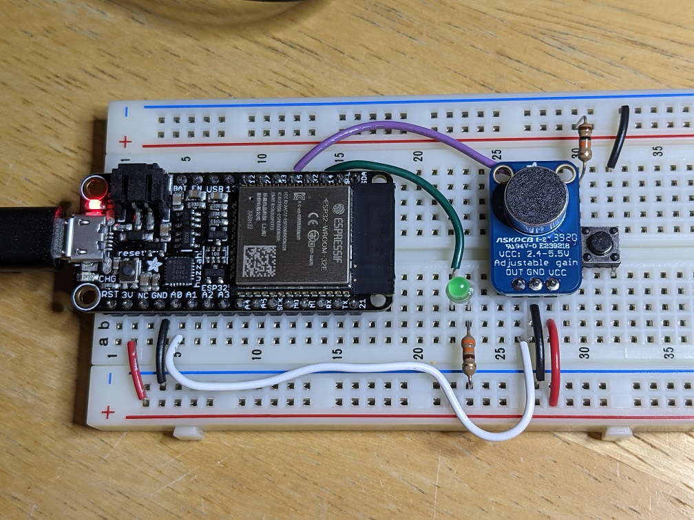 The microphone breakout circuit diagram
Build the circuit and edit the delay in the AnalogReadSerial code so that, in the Serial Plotter, the data fills across the plot in about 5 seconds. Speak, whistle or clap into the microphone to visualize the sound.
The frequency of a high whistle is in the kilohertz range. To see the sine wave at this frequency, the sample rate of the analogRead() should be at least twice, or event better ten times, the frequency of the sine wave. But, decreasing the delay in the code will flood the computer with too much data to plot, and it will stutter or crash. To visualize the data better, read the data into an array of 1000 values, then print the 1000 values, using two different for() loops.
Serial
Serial communication is a digital, two wire method of sending and receiving text data between two devices. Laptops no longer have physical serial ports, but USB communication can emulate the data transfer. When you plug an Arduino into a computer, a port name is created, like COM4 on Windows or tty.usbserial#### on Mac and Linux. Both devices are configured to send and receive data at a number of bits per second, or baud rate. If these numbers do not match, the data is misinterpreted and garbage.
To use serial communication on the Huzzah32, enable the module in setup() using Serial.begin(). To print text to the computer, use Serial.println(). The “ln” at the end of the print function sends the return character after the line of text is printed. If you want to print some text and the value of a variable, use the ‘ln’ only with the last print function.
For example,
Serial.print(“The value of i is “);
Serial.println(i);
Print a line of text containing the button and potentiometer data
Make a new file and initialize the serial and button pin functions. If the button is pressed, read the value of the potentiometer and print it to the computer as “Pot Voltage= “ and the value in volts. Open the serial monitor and press the button a few times. Do you notice any repeated prints? Any problems converting the integer number from analogRead() to a floating point number as volts?
Read text from the monitor
You can send text to the Huzzah32 using the serial monitor by typing in the textbox and pressing send. The data is sent one letter at a time. The function Serial.available() returns if any letters are available to read on the Huzzah32, and can be read with char c = Serial.read().
Wait for a character, collect potentiometer data and plot
Make a new file and write some code to send 100 values from the potentiometer at 100Hz after reading a “r” from the Serial Monitor. Try running it from the Serial Plotter as well.
RC Servo
A servo motor is a generic term for a motor that has an integrated position sensor, driver, and controller. Servos are used in all kinds of motion control. An RC servo is a small motor used in remote control cars, planes and boats, and is easy to command using a microcontroller. The Huzzah32 can command the RC servo to move to any angle from 0 to 180 degrees, and the servo will hold that angle as best as it can. Servos come in many sizes and qualities, and are often highly geared to have lots of torque. The downside of the gears is audible noise when moving. Most servos use a potentiometer as a position sensor, and this limits their motion from 0 to 180 degrees. The output shaft of the servo attaches to a part called the servo horn, which can be tricky to attach to. Try not to glue directly to it (the plastic is too inert for anything to stick well), instead use a stiff wire as a pushrod.
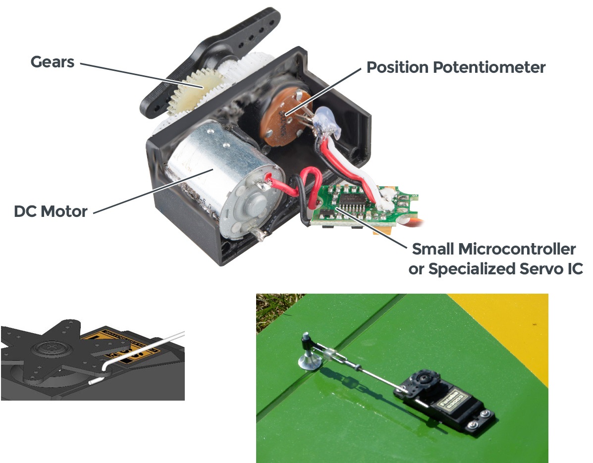 The RC servo
Wire up the RC servo, run the sweep example
The RC servo has 3 wires: brown for ground, red for 5V, and orange for signal. You can find 5V from the Huzzah32 on pin USB. Some larger servos can use more current than the USB cable can provide, and would need an external power source from a wall adapter or a battery pack. The kit contains a set of 3 extra long header pins so you can plug the servo into the breadboard (should already be stuck in the servo cable).
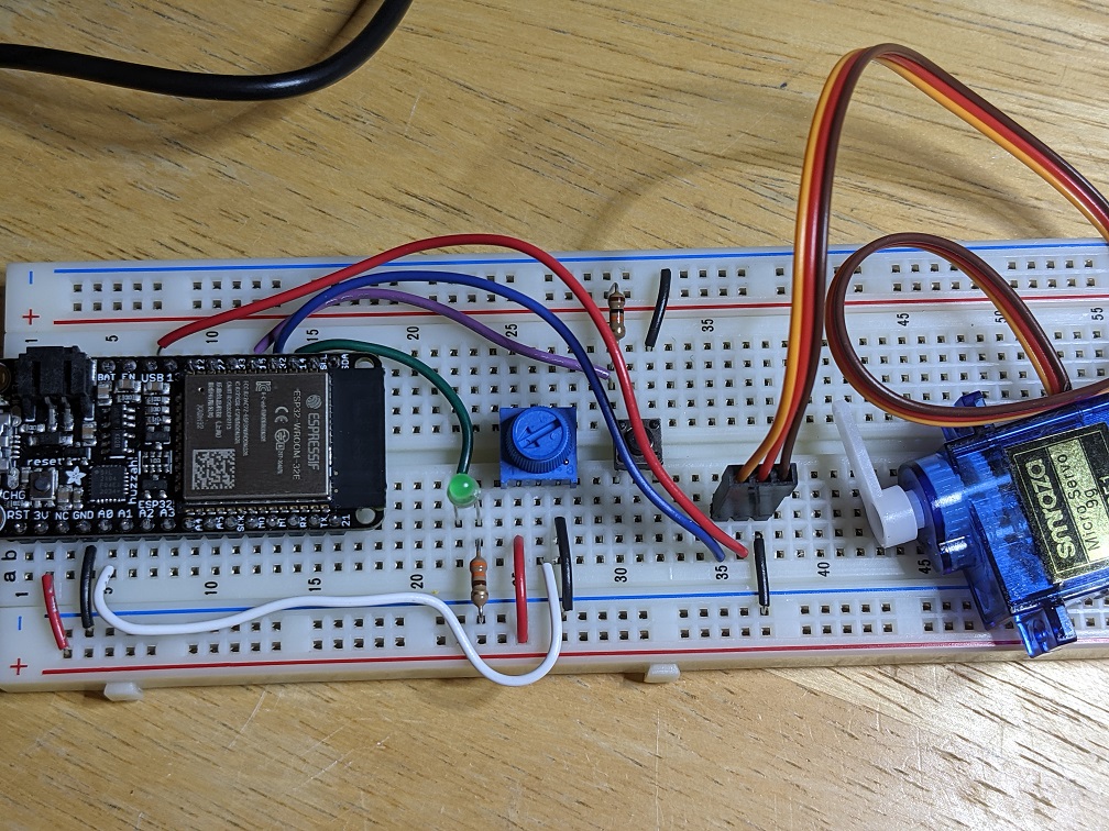 How to plug the RC servo into the breadboard
The servo is commanded using the PWM, like how analogWrite() pins work, so choose a PWM capable pin for the orange signal wire.
The code that the Huzzah32 uses to command the servo is not automatically included, so you need to include the library at the top of your code with #include <Servo.h>. In the definitions area, a servo variable type is declared, and in setup(), set the pin using myservo.attach(). Then you can command an angle using myservo.write(), which takes a number from 0 to 180 degrees.
Open the example code for the servo in File->Examples->Servo->Sweep. Change the pin and run the code and the servo should oscillate back and forth.
Make the servo motion mirror the potentiometer
Make a new file and copy in the contents of Sweep. Edit the code so that at 10Hz the potentiometer angle is read and sent to the servo, so that the servo angle matches the potentiometer angle.
Neopixel
We can set the brightness of a single color of LED using the analogWrite() function. How can we control a full color RGB LED, or a lot of LEDs, without using all the pins of the Huzzah32? A Neopixel is a brand of WS2812B RGB LEDs that can be controlled with a single pin, and chained so that a whole strip can be controlled individually for brightness and color, still using just one pin. Neopixels can be purchased individually, on long strands, and in all kinds of arrays of shapes.
Wire the Neopixel
The Neopixel board in the kit takes 5V, ground, and any pin for DIN (I used pin 5). The other end of the board has pads to solder connections to the next set of Neopixels, connecting DOUT to the next DIN. I have pre-soldered header pins on so you can plug the board into your breadboard.
Get the library
The Arduino IDE does not come with the code that the Huzzah32 needs to control the Neopixels, so you need to download and add it from an external library. INSTRUCTIONS FOR FASTLED
Run the example code
The Huzzah32 can drive many, many Neopixels, but we have only 8, so we need to change the example code to match. Change numPins to 1, edit the array pinList to just the number of the pin you are using for DIN, and change ledsPerStrip to 8. Run the code and the LEDs should flash through a variety of bright colors.
The Neopixels can be harshly bright, so I like to put something over them to diffuse the color, like a sheet of white paper, tissue, or cotton.
The code boils down to the ability to set the color of each LED individually using leds.setPixel(), and then telling all of the LEDs to update at the same time using leds.show().
Take a look at this sample code to see how to flash all the LEDs red, then green, then blue:
Set the brightness and color of each LED
You can also specify the raw RGB value of each LED. In this example, the value of the pot determines how bright white the entire strip of LEDs are:
IMU
An inertial measurement unit, or IMU, is a MEMS device that reads the acceleration and angular velocity of a device. It can be used to measure motion, like step count, or which way is down, for screen orientation. Most IMUs use digital communication like serial called I2C or SPI to communicate their data. The IMU in the kit is an acceleromter from Adafruit. Download and install the library from this GITHUB
Connect the IMU
The IMU break needs 4 connections: 3.3V to VDD, ground to VSS, and the data pins, SDA to the Huzzah32 SDA1 and SCL to the Huzzah32 SCL1.
Plot the data
The IMU has many settings, but for simple use, include the library at the top of the code, initialize the IMU in setup(), and read the data with imu.read(). The values returned for acceleration range from -32000 to +32000, where +16000 is 1g of acceleration. -16000 is -1g, or completely downwards.
Make a new file and read the accelerometer data 30 times per second, printing the X Y and Z acceleration values in three columns separated by spaces. View the data with the serial plotter.
 IMU data on the serial plotter
Set the brightness of the Neopixels to the data
Adjust the code so that if the IMU is tapped in the X direction, the Neopixel strip lights up green. If tapped in Y, Red, and tapped in Z, blue.
Sound
The Huzzah32 has a digital to analog converter to generate a voltage that can be amplified and played through a speaker. Your kit has two amplifiers and speakers, try each and compare how loud they can get and their noise (hiss) levels.
Get a file on the Huzzah32
There are many types of files that store sound data. Most are compressed and require a complicated algorithm to decompress and play in real time. Instead, let's use the .wav file type, which is literally an uncompressed array of voltages that represets the sound, so it is not size effieicnet, but easy for the Huzzah32 to play.
The Huzzah32 has 8MB of extra flash memory where you can store your sound. Playing back at a standard 44kHz and 16bit depth, that would store 90 seconds of sound. So, you can;t store an entire song, but you can store a few short sound clips.
Load the following .wav files using this utility.
Wire up the audio amplifier and speaker
The speaker requires an amplifier to produce loud and clear sound. The I2S amplifier receives the sound from the Huzzah32 digitally, resulting in less scratchy noise from the speaker. Connect the amplifier ground to ground, 5V to 5V, MISO to MISO, and MOSI to MOSI. I have pre-soldered wires onto the speaker. Connect the speaker wires to the amplifier in the green screw terminals.
 Speaker circuit
Play the sound
It takes several libraries to play the .wav files using I2S.
Play the sound and use potentiometer volume
Write some code that plays a sound when the IMU is tapped, and read from the pot to set the volume.
Capacitive Touch
Long Distance Sensing
Proximity, Light and Gesture
Going Mobile
Bluetooth
Wifi
Solutions
Button and LED
int led = 14;
int but = 15;

void setup() {
  pinMode(led, OUTPUT);
  pinMode(but, INPUT);
}

void loop() {
  if (digitalRead(but) == LOW){
    digitalWrite(led, HIGH);
  }
  else {
    digitalWrite(led, LOW);
  }
}
Toggle
int led = 14; // led pin
int but = 15; // button pin
int but_state = 1; // state of button
int prev_but = 1; // previous loop button state
int led_state = 0; // state of led

void setup() {
  pinMode(led, OUTPUT);
  pinMode(but, INPUT);
}

void loop() {
  but_state = digitalRead(but); // read the button
  // if the button was just pressed
  if (but_state == 0 && prev_but == 1){
    // toggle the led
    if (led_state == 0){
      led_state = 1;
    }
    else {
      led_state = 0;
    }
  }

  if (led_state == 1){
    digitalWrite(led, HIGH);
  }
  else {
    digitalWrite(led,LOW);
  }
  // remember the button state
  prev_but = but_state;
}
Interrupt
int led = 14; // led pin
int but = 15; // button pin
volatile int led_state = 0; // variables used in intterupts must be declared volatile

void setup() {
  pinMode(led, OUTPUT);
  pinMode(but, INPUT);
  // when but pin goes HIGH to LOW call the function but_pressed()
  attachInterrupt(digitalPinToInterrupt(but), but_pressed, FALLING);
}

void loop() {
  if (led_state == 1) {
    digitalWrite(led, HIGH);
  }
  else {
    digitalWrite(led, LOW);
  }
}

void but_pressed() {
  if (led_state == 1) {
    led_state = 0;
  }
  else {
    led_state = 1;
  }
}
Pot LED Dimmer
int led = 14; // led pin

void setup() {
  Serial.begin(9600);

  // configure LED PWM functionalitites
  ledcSetup(0, 5000, 8); // ledChannel, freq, resolution

  // attach the channel to the GPIO to be controlled
  ledcAttachPin(led, 0); // ledPin, ledChannel
}

void loop() {
  int sensorValue = analogRead(A0);
  Serial.println(sensorValue);
  //analogWrite(led, sensorValue/16); // this is how most other Arduino work
  ledcWrite(0, sensorValue/16); // ledChannel, dutyCycle
  delay(10);
}
Mic 1000 values
void setup() {
  Serial.begin(115200); // use a faster baud when sending a lot of data fast
}

void loop() {
  int sensorValues[1000]; // an array to store the data
  int i = 0; // an index to remember where you are in the array

  // get 1000 data points
  for(i=0; i<1000; i++){
    sensorValues[i] = analogRead(A0);
    delayMicroseconds(10); // 10us delay = 100kHz sampling
  }

  // send the data to the computer
  for(i=0; i<1000; i++){
    Serial.println(sensorValues[i]);
  }

  // wait half a second so the user can see the plot
  delay(500);
}
Serial Pot Button
int but = 15; // button pin

void setup() {
  Serial.begin(9600);
  pinMode(but, INPUT);
}

void loop() {
  if (digitalRead(but) == LOW){
    Serial.print("Pot V = ");
    Serial.println(analogRead(A0)*3.3/4095); // be careful fixing int and float math!
  }

  delay(10);
}
Serial Read
void setup() {
  Serial.begin(9600);
}

void loop() {
  if (Serial.available()){
    char c = Serial.read();
    if (c == 'r'){
      int i = 0;
      for (i=0; i<100; i++){
        Serial.println(analogRead(A0));
        delay(10);
      }
    }
  }
}
Servo Potentiometer
#include <Servo.h>

Servo myservo;

void setup()
{
  myservo.attach(33);
}

void loop()
{
  int pot = analogRead(A0);
  int pos = map(pot, 0, 1023, 0, 180);
  myservo.write(pos);
  delay(100);
}
Neopixels
#include <OctoWS2811.h>

const int numPins = 1;
byte pinList[numPins] = {34};
const int ledsPerStrip = 8;
DMAMEM int displayMemory[ledsPerStrip * numPins * 3 / 4];
int drawingMemory[ledsPerStrip * numPins * 3 / 4];
const int config = WS2811_GRB | WS2811_800kHz;
OctoWS2811 leds(ledsPerStrip, displayMemory, drawingMemory, config, numPins, pinList);

#define RED    0xFF0000
#define GREEN  0x00FF00
#define BLUE   0x0000FF
#define YELLOW 0xFFFF00
#define PINK   0xFF1088
#define ORANGE 0xE05800
#define WHITE  0xFFFFFF

void setup() {
  leds.begin();
  leds.show();
}

void loop() {
  int i;
  for (i = 0; i < leds.numPixels(); i++) {
    leds.setPixel(i, RED);
  }
  leds.show();
  delay(1000);

  for (i = 0; i < leds.numPixels(); i++) {
    leds.setPixel(i, GREEN);
  }
  leds.show();
  delay(1000);

  for (i = 0; i < leds.numPixels(); i++) {
    leds.setPixel(i, BLUE);
  }
  leds.show();
  delay(1000);
}
Neopixels Potentiometer
#include <OctoWS2811.h>

const int numPins = 1;
byte pinList[numPins] = {34};
const int ledsPerStrip = 8;
DMAMEM int displayMemory[ledsPerStrip * numPins * 3 / 4];
int drawingMemory[ledsPerStrip * numPins * 3 / 4];
const int config = WS2811_GRB | WS2811_800kHz;
OctoWS2811 leds(ledsPerStrip, displayMemory, drawingMemory, config, numPins, pinList);

void setup() {
  leds.begin();
  leds.show();
}

void loop() {
  int i;
  int brite = analogRead(A0)/4;
  for (i = 0; i < leds.numPixels(); i++) {
    leds.setPixel(i, Color(brite, brite, brite)); // BRG for some reason
  }
  leds.show();
  delay(10);
}

unsigned int Color(byte b, byte r, byte g)
{
  return ( ((unsigned int)r & 0xFF ) << 16 | ((unsigned int)g & 0xFF) << 8 | (unsigned int)b & 0xFF);
}
IMU Plot
{{#include ./code/huzzah32-imu-plot.c}}
IMU Neopixel
{{#include ./code/huzzah32-imu-neopixels.c}}
Play Sound
{{#include ./code/huzzah32-play-sound.c}}
Appendix
What you may have missed by using just the lab kit
Your lab kit just scratches the surface of possible parts that can be used with the Teensy. There are also lots of tools that can be helpful for design and debugging that could not be included for price and size reasons.
The Mechatronics Design Lab at Northwestern University has 8 lab benches with variable power supplies, oscilloscopes, function generators, benchtop multimeters, and more. When it is safe to do so, please stop by to check it out.
Soldering
A good mechatronics bootcamp should include the opportunity to solder some components. When you have prototyped a circuit and are ready to move to a more permanent device, the breadboard can be replaced by a solder-able protoboard or a custom designed printed circuit board. These require the components to be soldered to be reliable.
Soldering is the act of welding electrical components with solder for the purposes of electrical conductivity (there is also a version of soldering to make a mechanical joint, like in a pipe, electrical soldering is much lower energy process). Soldering uses a 30W iron in the shape of a pencil (not a gun or torch, those have other uses). To solder, mate the two conductors, heat them to the melting temperature of solder using the iron, and apply solder. Soldering is all about heat transfer: if the conductors are not hot enough, the solder will not melt and wick into the joint. To aid in transferring heat from the iron to the conductors, solder is applied to the tip of the iron because the liquid solder bubble transfers heat more effectively than dry metal-to-metal contact. The solder bubble does not leave the iron tip, it is only there to help with heat transfer! Solder is not applied like glue in that way.
When you get a chance to try it out, try:
- Solder two wires together
- Solder the strands of a stranded wire into a solid wire
- Solder a resistor into a solder-able protoboard
- Remove a component from protoboard and suck out the solder
- Solder header pins into a breakout board
3d printing and Laser cutting
Most projects will need some mechanical parts and an enclosure to house the electronics. There are lots of pre-made boxes available, but with a little time invested in learning computer aided design (CAD) you can model custom parts and use rapid prototyping tools to create them. It is tempting to 3d print everything, but laser cutting is usually faster and more effective, especially for parts that are mostly made of flat surfaces. Don’t let me catch you printing a box! Those should be made with the laser cutter.
PCB design
A printed circuit board can be manufactured and delivered in as little as a week for under $50. It makes a prototype much more reliable and professional looking. Check out these tutorials for using Eagle CAD to draw a PCB.
Links
- Arduino code reference
- Teensy website
- General C help
Where to find parts
There are many websites that sell “breakout boards” for components that cannot be plugged into a breadboard. Before you buy, make sure the vendor has some sample code available.
-
Sparkfun Sells a nice array of Arduino and Raspberry Pi compatible parts
-
Adafruit Has very nice tutorials for all of their parts, strongly supports Circuit Python (using python to program the microcontroller instead of C)
-
Pololu Has nice sensor boards and high quality motors and motor drivers
-
Servo City Lots of different sizes of servos and servo attachments
-
Seeed Like Sparkfun and Adafruit, but pay attention to the shipping times
-
Hobbyking More powerful motors and moor drivers, lot of random parts, make sure to ship from a US warehouse
-
Digikey / Mouser / Newark Sources for low level components and an alternate supplier for the above vendors
-
Amazon Lots of stuff here but sometimes a low price is a knockoff part, also pay attention to weird shipping times
-
Aliexpress The best source for parts in higher quantities, but expect expensive or long shipping times