MPD2 Programming and Mechatronics Boot Camp 2020
By Nick Marchuk
A manual for the programming and mechatronics portion of boot camp, MPD2 2020.
Before the Programming and Mechatronics Sessions
We will be using the ItsyBitsy M0 Express, programmed with CircuitPython. You will need the mechatronics lab kit and a laptop with a USB port.
Please install:
- The Mu IDE (1.0.3) from https://codewith.mu/en/
Foreword
MPD2 Boot Camp is a great way to start the year. I always look forward to the creative projects and new faces.
2020 will not be the typical year, but we will make the best of it. Normally I would not provide so much written material, so hopefully you will find this manual useful long after the quarter starts. If anything is missing, confusing, or flat out wrong, let me know!
Introduction to Programming and Mechatronics
Who am I and where to find me
This manual is written by Nick Marchuk, Senior Lecturer in Mechanical Engineering at the McCormick School of Engineering and Applied Science at Northwestern University in Evanston, IL. Nick runs the Mechatronics Design Lab in the Ford Building, right next to the Prototyping Shop. The Mechatronics Lab contains oscilloscopes, power supplies, multimeters, function generators, soldering irons, 3d printers, and parts like wire, buttons, LEDs, and ICs. The lab is open on weekdays from 9am-6pm, and available 24 hours with wildcard access. Nick’s office is in the back of the lab, and Nick is available for open office hours every day according to the schedule posted on the door. (Please check with Nick for updated lab and office hours during Covid).
Nick can be reached at nick.marchuk at u.northwestern.edu
Hands-on philosophy
Welcome to the Programming and Mechatronics portion of boot camp! This guide will introduce you to Python programming, the parts in your lab kit, how to build circuits, CircuitPython programming, and the design process for electromechanical projects. You don’t need experience in any of these topics to get started! But you do need some desk space, a laptop, and some nimble fingers, because this is hands-on exploration and play time. Each section of this manual will guide you through a topic, show you one way to build a project, and then ask you to give it a try for yourself. Some solutions can be found at the end of the manual. It is important that you attempt to solve the exercises first, before jumping to the solution. The best way to use this material is to get your hands dirty, that’s where most of the learning happens!
How to get help
Whether you are in boot camp or you happened upon this guide online, you are probably working on it remotely. This is definitely not the ideal situation. A second set of hands and eyes, especially ones with experience, can make the difference between a fun and a frustrating project. Just remember that it is all part of the learning experience. In fact, the skill you will be practicing most is debugging. Usually debugging is associated with computer programming, but it can be applied to almost any task. Debugging is a “soft” skill, a process that must be experienced rather than taught. This manual will point out some techniques as it goes, but your best option is be methodical: document your work as you go, test as you build, and keep an open mind.
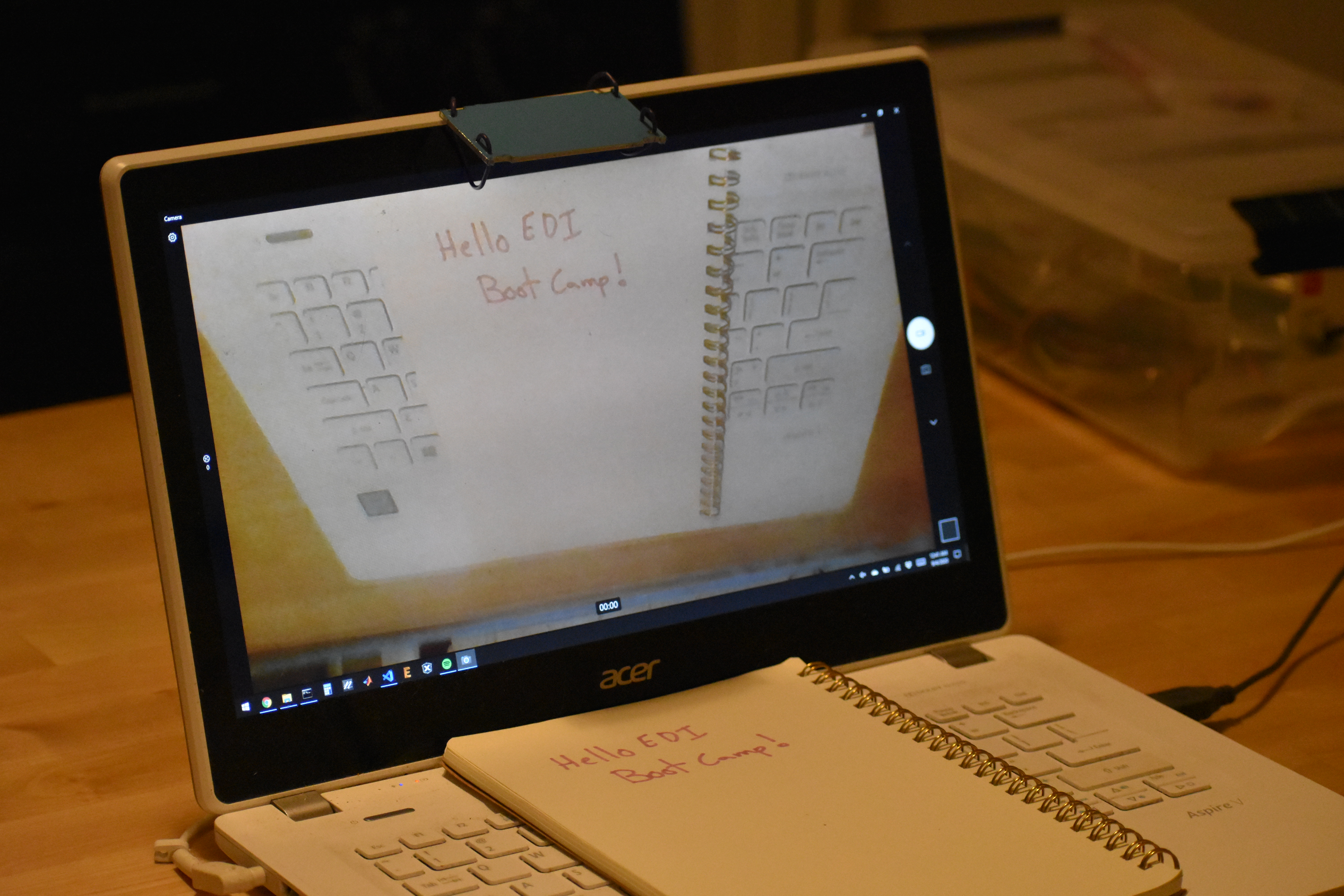
Bootcampers will be able to take advantage of online office hours using Zoom. Please come prepared with a circuit diagram and your physical circuit. How can you share these? A document camera! But these can be expensive and hard to find, and you already have all the parts you need to make your own.
The Northwestern Mirror Document Camera
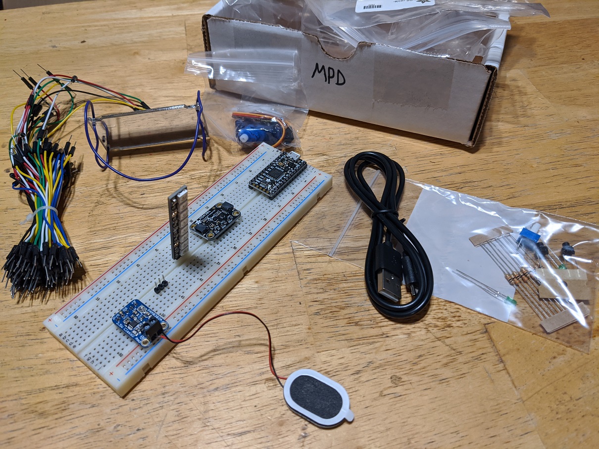
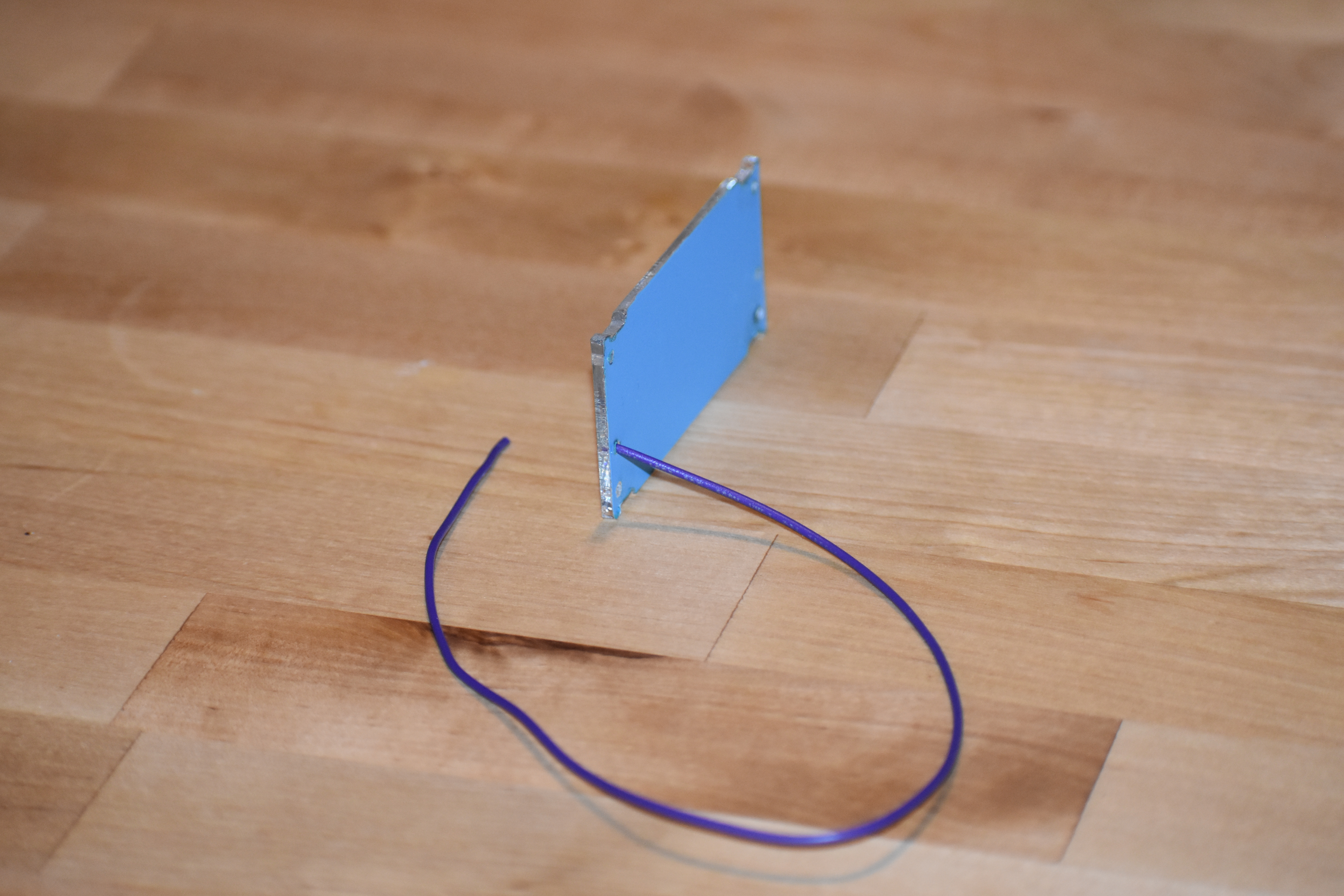
The first exercise is to assemble your document camera. You will need the small acrylic mirror and the 22 gauge purple wire from your kit.
 Mirror Document Camera parts
The wire will wrap around both sides of the mirror, holding it onto your laptop screen in front of the webcam, reflecting the keyboard onto the mirror, and allowing you to place your circuit or drawing on your keyboard to share with your webcam.
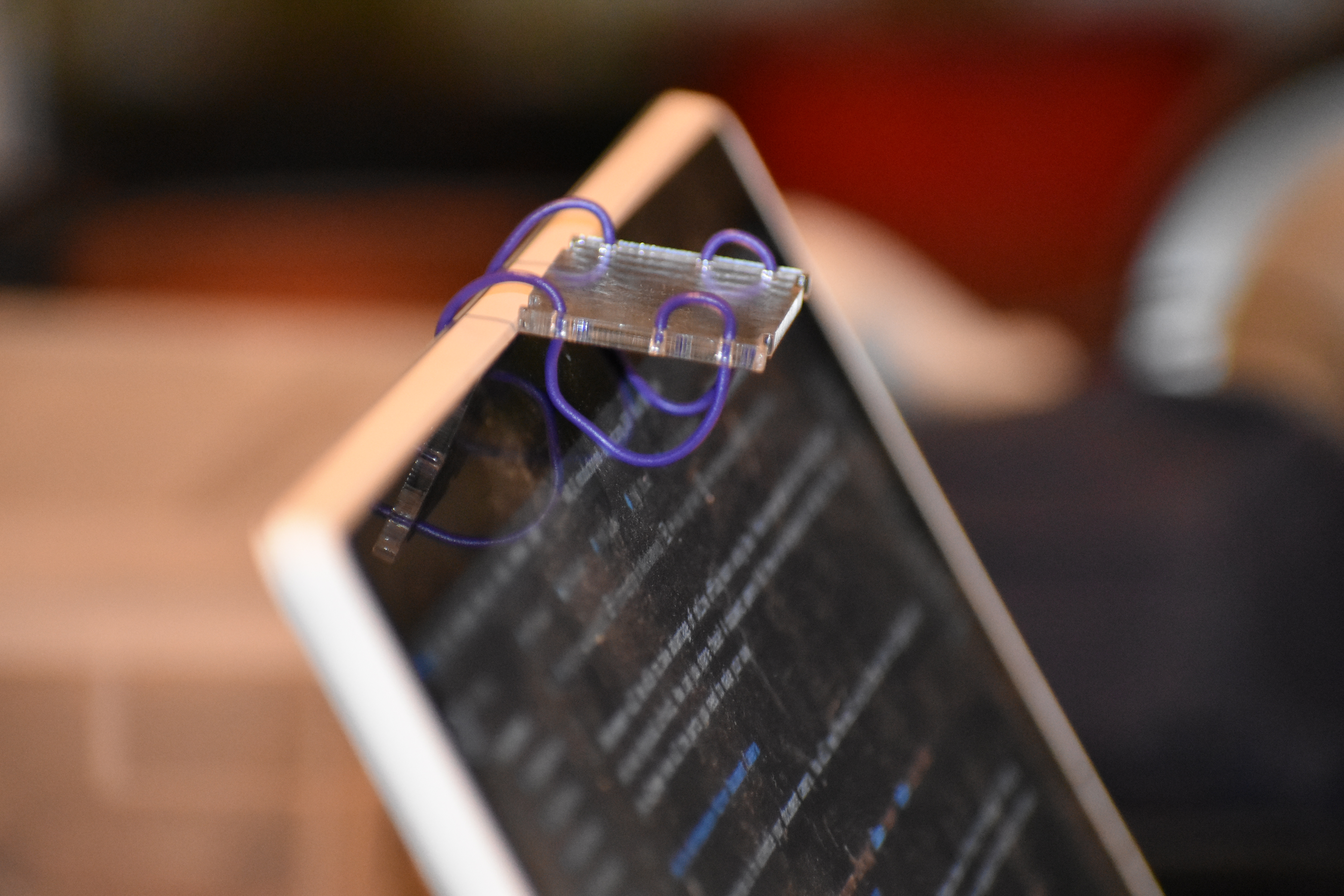 Mirror Document Camera assembled
Using the annotation tool in Zoom, the instructor can draw on the image of the circuit and help debug!
Assembly instructions:
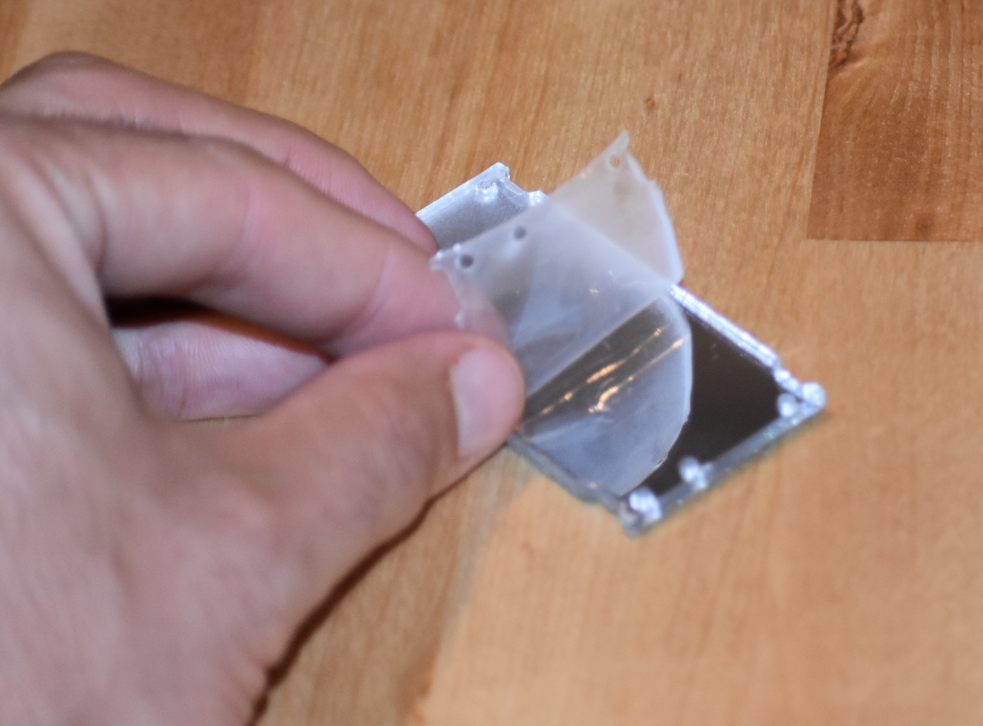
- Remove the clear plastic film from the surface of the mirror, and pop out any bits of plastic that are stuck in the six holes
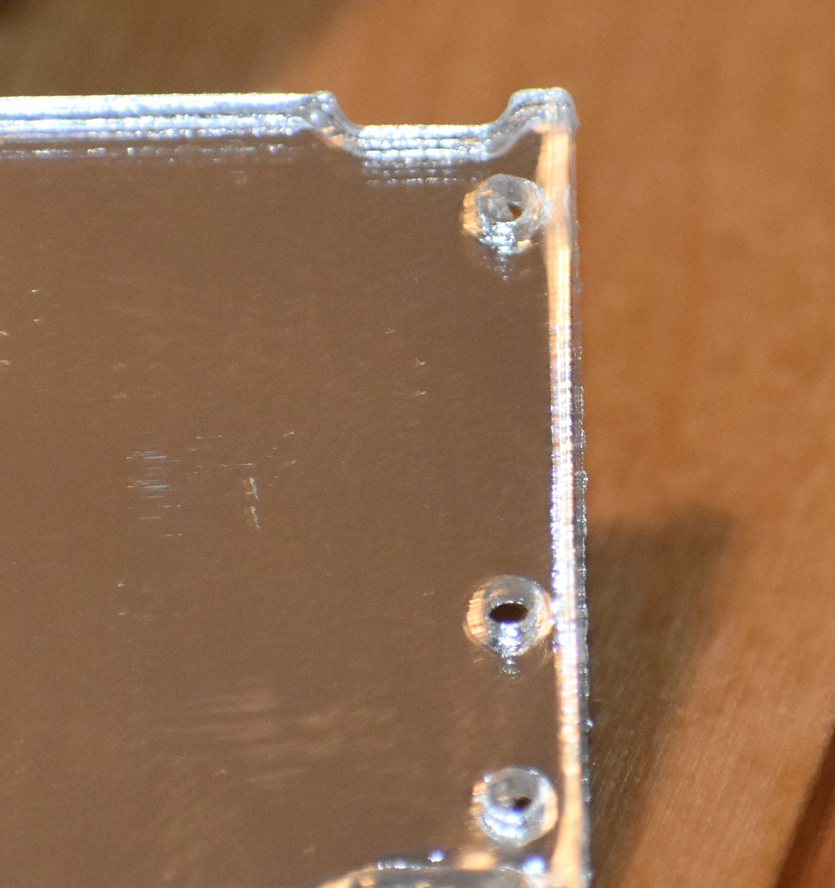
- Stick one end of the wire into the middle hole from the blue side
- Wrap the wire through the closer hole, tight against the blue side
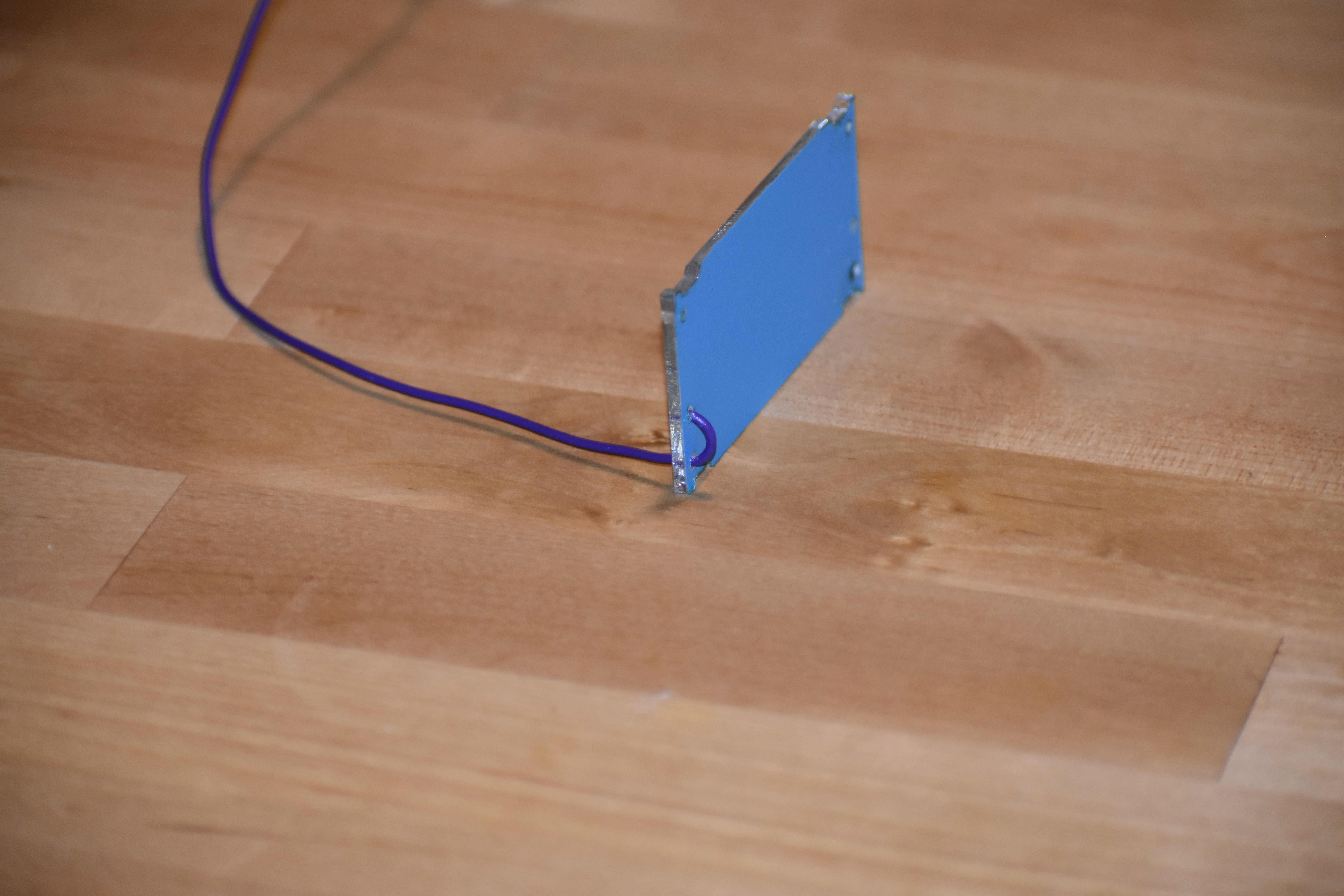
-
Loop the wire through the further hole, leaving about an inch between the loop and the mirror
-
Continue to feed the wire though the other side of the mirror, leaving a large loop in the middle
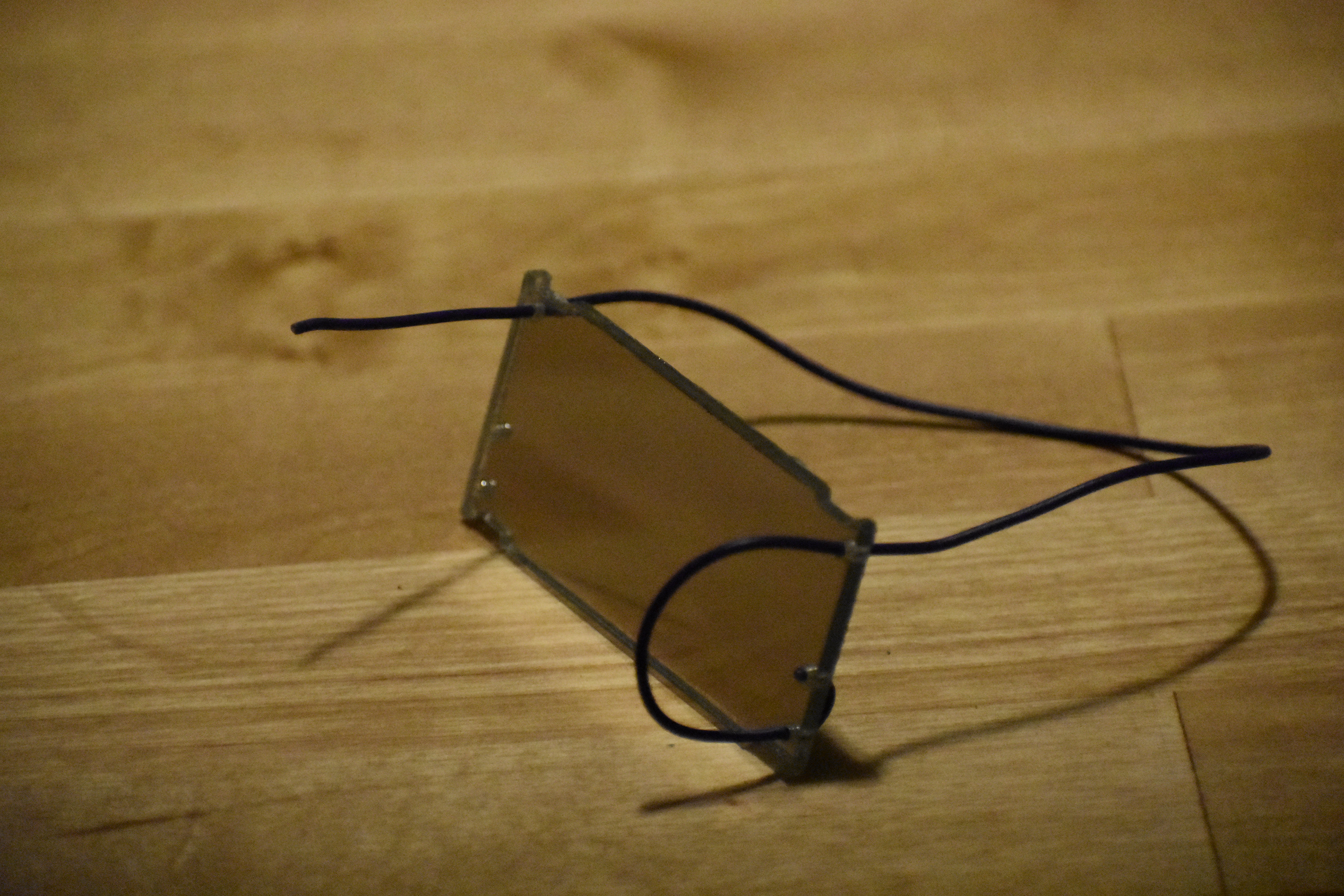
- Form a one inch loop through the bottom hole and end the wire in the middle hole
-
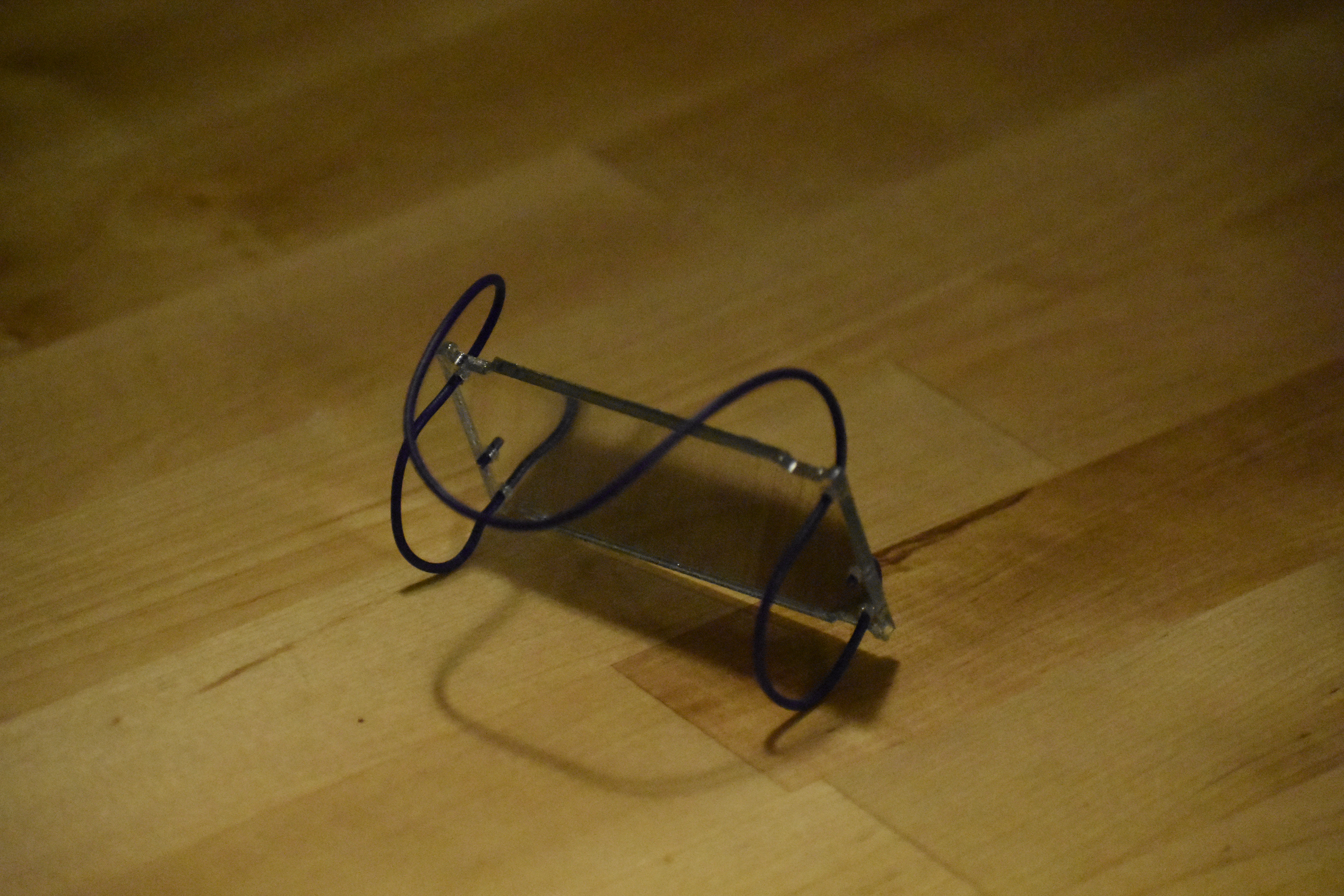
Mount the mirror on your laptop screen in front of the webcam, adjusting the large loop around the back of the screen and the small loops in the front so that the camera is at about 45 degrees from the screen
-
Open your camera app and adjust the mirror for the best view of your keyboard
Now we are ready to get to work!
Mechatronics and rapid prototyping
Mechatronics is the field of electromechanical design. It combines mechanical engineering of the physical design, electrical engineering of the sensors, drivers, and actuators, computer science of programming the code, and control theory for the design of the algorithms that lead from sensing to actuating.
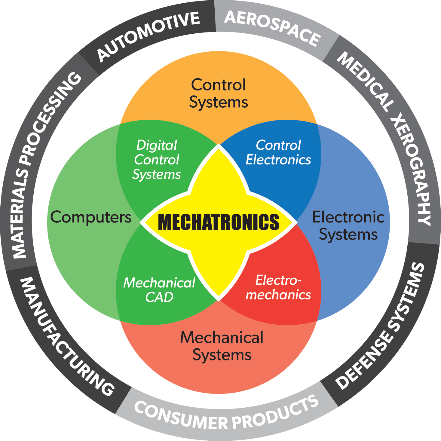 The Mechatronics venn diagram
You interact with mechatronic objects all the time. A microwave, a cell phone, and a car are all examples of mechatronic objects. Their design can be slick and smooth or chunky and obfuscated. They can also be tiny, expensive, and complicated, all of which point to objects that take lots of experts and time to design and build. But this is not necessarily the case. Hobbyist tools and open source software have reduced the barrier to entry to such low levels that mechatronics has become accessible to anyone with a laptop and the internet. Ideas that previously were left sketched out on the back of a napkin can now be whipped up with microcontroller dev kits and 3d printers in a matter of hours instead of weeks in a process referred to as rapid prototyping.
Arduino and CircuitPython
The tool that makes this all possible is Arduino. Before Arduino, electronic development tools were expensive and proprietary. The Arduino project, started at MIT, developed open source software and hardware that took advantage of the power of a laptop to allow everyone to write and compile code and place it on a low cost USB powered device. This spawned a DIY revolution that has created low cost 3d printers, inexpensive drones, and a dozen companies that cater to the community with an endless supply of cool sensors, LEDs, motors, and sample code.
“Arduino” is a loose term to describe the program where you write your code, a name for the electronic board that runs the code, and the code itself. But technically the program is an IDE, and there are several that you can choose to use, not just the official Arduino IDE. There are many brands of microcontroller boards that can be programmed using the IDE, not just official Arduino boards. And the code is technically C++.
C++ is a hurdle because of it has steep learning curve. Arduino does it's best to simplify the code and compiling process, but there are newer programming languages that are far easier and more popular, and just now finding their way onto Arduino-style microcontroller boards. The language we will use is Python, specifically a subset called CircuitPython, that runs on the ItsyBitsy brand of micrcontroller boards from Adafruit. CircuitPython code does not run as fast as C++, but for most projects you'll be up and running faster in Python and not notice the difference in loop time.
Other resources
The world of Arduino, CircuitPython, and accessible mechatronics would not exist without the dedicated DIY community behind it. You can find a list of our most commonly used suppliers and some great blogs in the Appendix.
Kit Parts List
- ItsyBitsy M0 Express
- Micro USB cable
- Neopixel stick
- Accelerometer
- Audio amplifier
- Speaker
- Breadboard
- Green LED
- Potentiometer
- Push button
- Resistors (330ohm, 10kOhm)
- RC servo
- Jumper Wire
Programming
The importance of programming
Computer programming is a skill that everyone can, and should, learn. Programs are useful for automating tasks, analyzing data, and mocking up and prototyping devices, and also for helping us break down and debug problems. The ability to think like a programmer is just one more tool in your box!
Progamming languages

There are many programming languages, each with important pros and cons. Compiled languages, like C++, run fast code, but take the longest to learn how to write. Statically interpreted languages, like Java, are cross-platform, are easier to write, but don't run as fast. Dynamically interpreted languages, like Python and Matlab, are the fastest to write, but run the slowest.
How programs are written
The process of writing a program starts with the development environment, or IDE. Popular IDEs are Visual Studio, Xcode, Netbeans, and Eclipse. Nice IDEs have helpful features like autocomplete.
Version Control
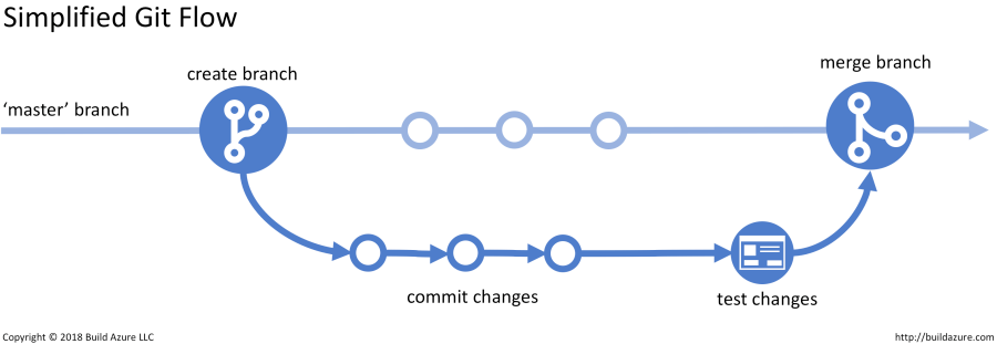
Most programs are written in collaboration. A lot of effort is put into making sure programmers can understand each other's code, and making sure big projects written by many people can be spliced together. Version control software, like git, is a standard way to identify who is working on what, merging changes, and identifying and fixing bugs.
Python
We will use Python to explore some introduction to programming. Python is a popular dynamic language (if you are familir with Matlab you'll see a lot of similarities). Python code is interpreted as it runs, so it is not a fast language, but it is easy to do lots of interesting things in Python with very little experience.
Python in the browser
One way to learn Python is to run it directly in your browser, for instance on trinket.io. Every week there are more websites like this that have tutorials and code as you go lessons, with nothing to download!
Python on your computer
The most reliable way to run Python is by installing it on your computer. Python itself is very lightweight, the real power comes from add-on libraries that do statistics, make graphics, and do machine learning. You can download Python and the most popular libraries using Anaconda.
Python using Mu
But we'll use something a little simpler, a program called Mu (pronounced moo), from https://codewith.mu/en/. Mu let's you program traditional Python, and also CircuitPython on microcontrollers, and games using Pygame Zero. It installs Python 3 and some common libraries. Mu is an IDE with some basic debugging tools, plenty to get started with.
Open Mu and click the Mode button in the top left. Select Python 3. You can see the text window with a comment, and some buttons, like Run. Python files are saved with the extension .py.
Repl mode
As a dynamic language, you can run Python one line at a time, without even needing to write a .py file. This mode is called REPL, or read-evaluate-print-loop. Click the REPL button and you'll see a line at the bottom that says In [1]:. There you can type lines of Python, one at a time, and see what happens. Try making a variable, like a=4, and pressing enter. Then press a and enter, and Python will tell you the value of a. Pretty neat!
Try doing some math. Do fractions work like decimals or integers? What happens when you divide by 0?
Make an array (in Python called a list) like c=[1,2,3]. What is the value of c[1]? What is the value of c[-1]?
Python built-in functions
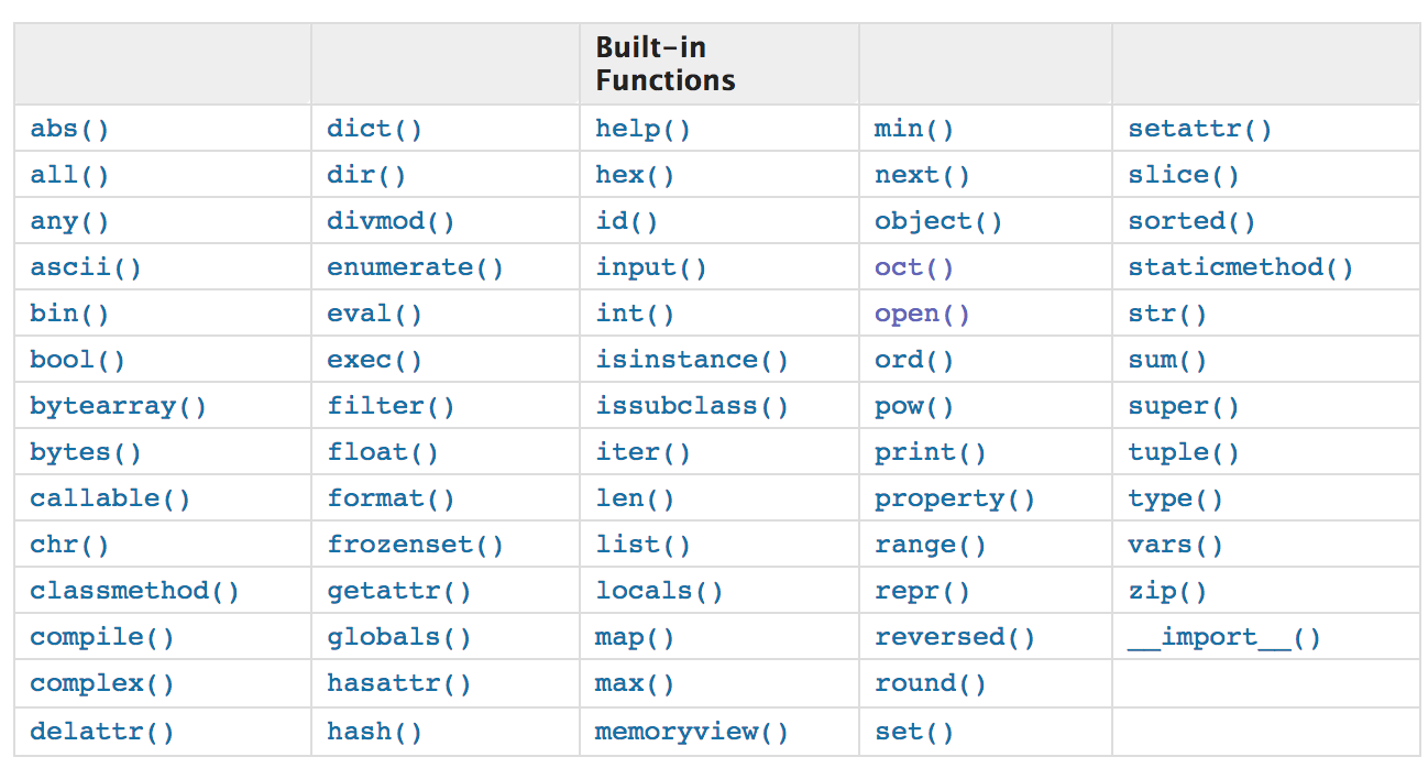
Python has a limited set of built-in functions. Try using print() on a list. Try using sum() on a list. Try making a list with letters and numbers, like k=[1,'t',3]. What happens when you sum(k)? How do you sum 't' and 1?
Python conditional statements
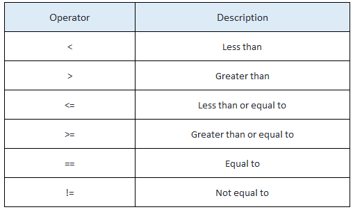
So far it looks like Python is a fancy calculator. As a programming language, it can run special syntax to do comparisons and loops. Try an if() statement. Note that statements like this end in : and the next line needs to be tabbed, and every line that should happen next is also tabbed.
Syntax
Repl mode is great for testing single lines of code, but to be efficient, we should write a program and save it as a .py file, then hit the Run and Stop buttons. Edit the file so that you make a variable and test its value using an if() statement. If the statement is true, print() something.
Edit the program to ask the user for a number, using the intput() function. Immediately turn the value into an integer using int(). If the value is 4, print Yes!
Write a function
If you find yourself using the same code over and over, you should probably turn it into a function. A function is a block of code that takes and input and returns an output. Functions go at the top of your file, using the def to start, and return to end. Try the following code:
def doubleIt(varIn):
    return varIn*2
def main():
    a = 2
    b = doubleIt(a)
    print(b)
main()
Python libraries
Libraries of extra functions are what makes Python so powerful. For example, NumPy has mean(), std(), etc. To add the NumPy library, use Import numpy, and then you can use the functions like numpy.mean(). Sometimes we shorted the name of the library to make less typing, so Import numpy as np, and then you can use np.mean().
Try making a list of numbers and taking the mean.
You can see the libraries installed with Mu in a folder that looks like C:\Users(username)\AppData\Local\Mu\pkgs.
Make a plot
The library matplotlib makes plots that look like Matlab plots, using similar syntax. Try:
import matplotlib.pyplot as plt
x = [1,2,3,4,5]
y = [6,7,8,9,0]
plt.plot(x,y,'ro-')
plt.show()
Loops
A while() loop will continue until its condition is met. A for() loop will perform an action a set number of times. Both can be used to iterate over lists or actions.
For example:
a=5
while a>0:
    print(a)
    a = a - 1
for x in range(5):
    print(x)
Use a for() loop to build a list that is the sine(t), then plot the list.
Import data from a file
One way to get data into Python is to save it as a comma separated file type (csv). Then you can loop through every row and analyze it. For example:
import csv
with open('data.csv') as f:
    reader = csv.reader(f)
    for row in reader:
        print(row)
This will print out the entire csv file.
Want to try something cool?
You can get the number of entries in every CTA train stop every day since 2001 from the CTA open data portal clink export->CSV (warning, 32Mb file size). Put the csv file in the same folder as your .py file (usually in a folder called mu_code).
The second element is the name of the station, and the fifth is how many entries there were that day.
Loop through and count how many entires there have been at Noyes since 2001:
total = 0
import csv
with open('cta2020.csv') as f:
    reader = csv.reader(f)
    for row in reader:
        data = row
        if (row[1] == 'Noyes'):
            total=total + int(row[4])
print(total)
Which station is busier, Foster or Noyes?
Circuit Building
Some students might never have built a circuit before, and others might have a degree in it, but let’s start at the beginning. The first topic to cover is how to build a circuit out of electrical components, wire, and a breadboard.
How the breadboard works
A breadboard is a plastic housing for lots of conductive metal springs. By plugging conductors like wire and the metal legs of components into the springs, current can flow through the circuit, and voltages are applied to make the circuit operate.
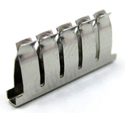 The spring clip inside the breadboard
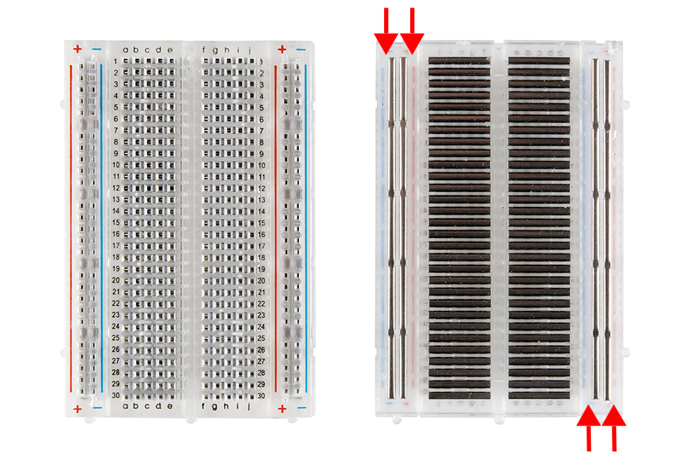 The breadboard and the arrangement of the clips inside
The matrix of holes are organized to assist in routing wires to different parts of the circuit. When a conductor touches another, they will have the same voltage. Often you want to share a voltage with several conductors, so the breadboard conductors are arranged to quickly expand access to a conductor by giving many access points via the holes.
The breadboard is three parts: two sides, and a larger center piece.
The center holes are connected as rows with 5 connected holes, and a break in the middle.
The sides of the breadboard, called the rails, are connected as long, uninterrupted columns.
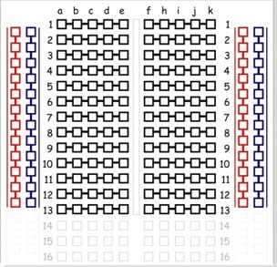 Breadboard internal layout
Each part of a circuit needs access to power and ground, so the rails are typically used to take the small number of power and ground pins from the source and give many access points to those voltages.
Cutting and stripping a wire
Circuits are built by connecting components together using conductor: wire! There are many types of wire, and with many sizes. The best wire for prototyping with a breadboard is 24 gauge, solid core insulated wire. The smaller the gauge, the thicker the wire and the more current it can supply without getting hot. Solid core wire is a single strand of wire that fits well into a breadboard. Stranded wire, usually 7 or 12 strands, is more flexible, the strands fray when getting plugged into a breadboard, so avoid using it for that purpose. The insulation prevents the wires from touching each other, and the color of the insulation should be used as a convention to remind you what the voltage or purpose of the wire is.
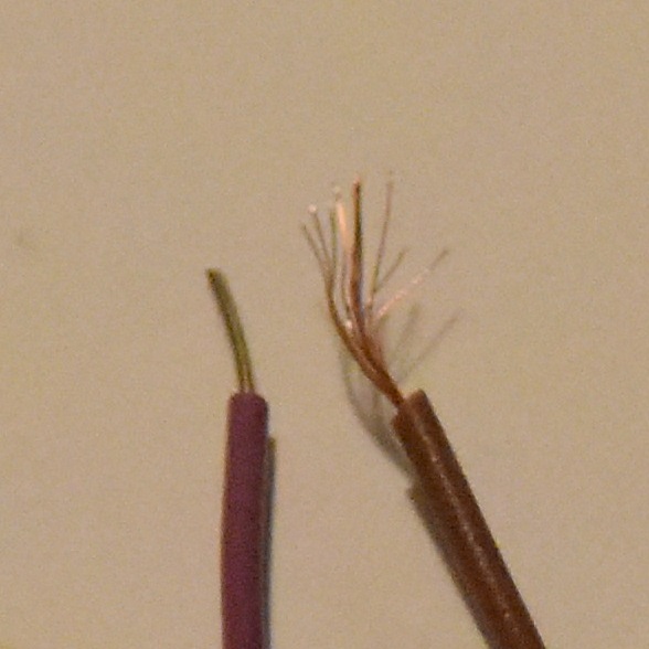 Solid and stranded wire
Prototyping wire is available as pre-cut and pre-bent kits, and as “male to male” wire. Your kit contains 65 pre-made male to male wires.
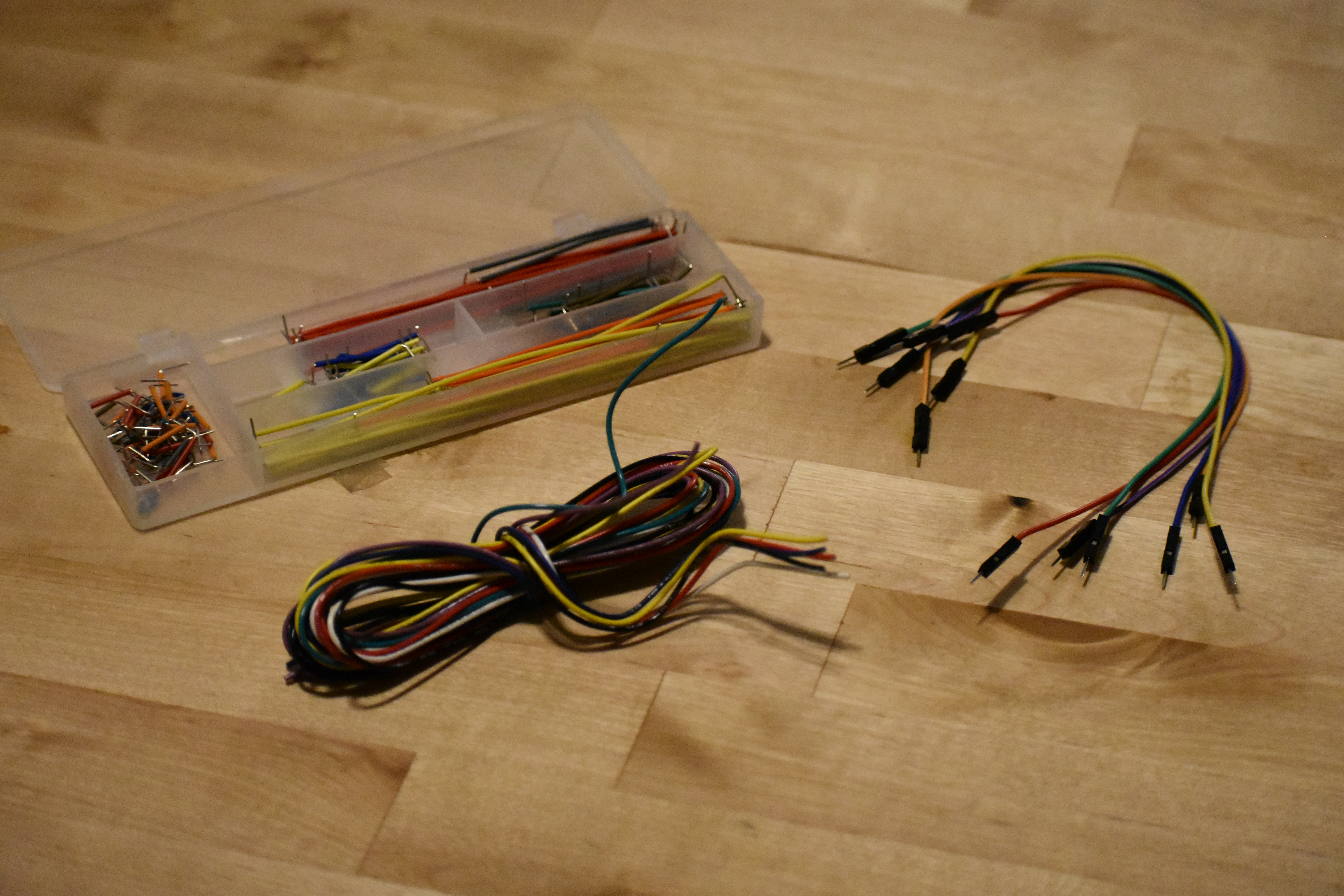 Wire kits
When you build a circuit, you should keep the wires color coded and in a “manhattan style”, or close to the board with 90 degree bends. The pre-cut and pre-bent wire kit is nice for keeping your circuit manhattan, but is hard to color code because each length of wire is a set color. The male to male headers are long, leaving long dangling wires that are easy to accidentally pull out.
Normally I wouldn't give you pre-made wires, I would force you to make your own from solid code wire, but because we are remote we'll cheat. Soild core wire is slightly less convenient than the other types of wire, but the organization and reliability are well worth it.
For reference: The base of the wire cutters is the cutter. Note that these cutters are only good for cutting wire, not other kinds of metal (they will get quickly destroyed if you try to cut a screw!) And don't use scissors to cut your wire, that will damage your scissors.
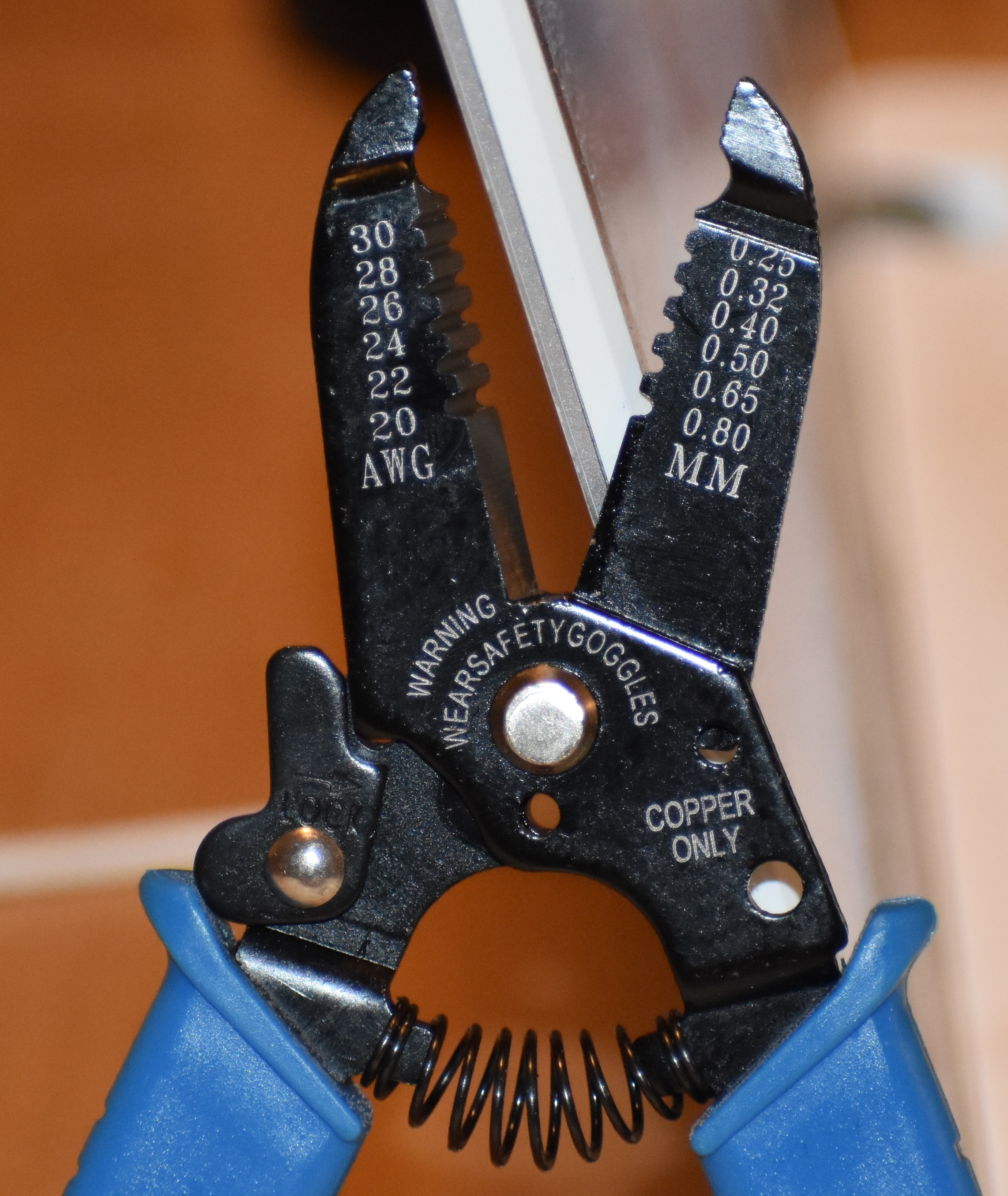 Wire cutters
TO remove the insulation from solid core wire, use the alligator tooth hole to cut through the insulation, but not cut the wire. If you use a hole that is too big, the insulation will not get cut and slide off. If you use a hole that is too small, the insulation will be cut through, but the wire will also be nicked, and that will eventually lead to the wire breaking at that point. Experiment a little and find the right size hole for your wire (this is experimentally because while the wire is 24 gauge, the wire strippers are inexpensive and your 24 size hole may be over or under ground, so you may need to use the 26 or 28.)
Use the ItsyBitsy as a power supply and turn on an LED
Your breadboard already has some parts plugged in, including the ItsyBitsy M0 Express. Keep the ItsyBitsy plugged in and remove the other parts for now. When removing large chips, be careful not to bend the pins as you remove the part. Lift a little from one side, then the other, until it comes out.
The ItsyBitsy gets power from a USB cable, and we can use the ItsyBitsy to power a circuit without any code. The ItsyBitsy pinout is a map that describes what each pin is capable of doing. Use it to locate the 3.3V pin and ground pin.
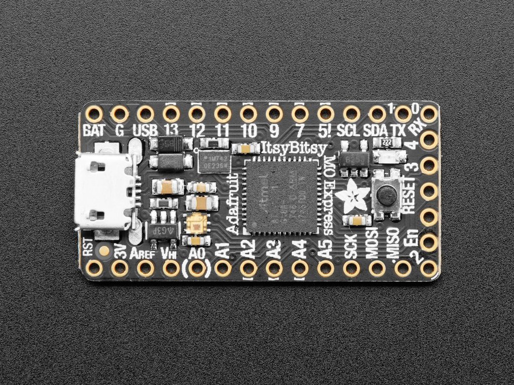 The ItsyBitsy M0 Express pinout. 3V is 3.3V, G is ground
Do not plug the USB cable in while building your circuits, just in case you accidentally touch wires that have different voltages and create a short. A short can damage the component, the ItsyBitsy, or your computer! (It is actually hard to damage your computer, as long as you are not using an external power supply or battery with your circuit.)
The rows that these pins are plugged into provide 3.3V and 0V. We will need more than these holes, so connect these rows to the rails. The wire color convention is to use black wire for ground, and red wire for power. Wire is wire, so it will work the same for every color, but using this color convention will make it easier to identify bugs later on. Connect the rails from one side of the board to the other along the bottom of the board, so that you have lots of holes that provide 3.3V and 0V on both sides.
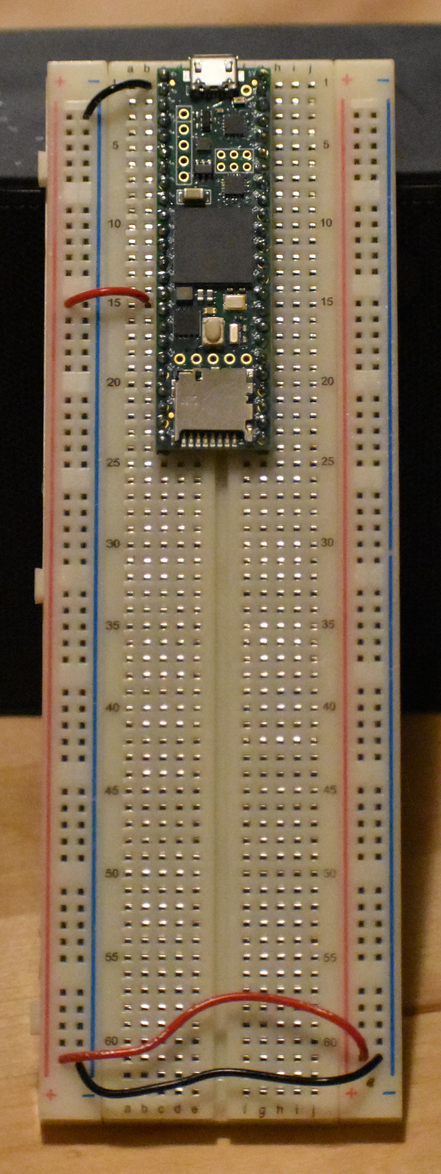 Power rails
Current flows from higher voltage to lower voltage, so a circuit built from 3.3V to 0V will allow current to from 3.3V to 0V. A short is defined as an infinite current, which would happen if you connected 3.3V to 0V using a wire (don’t do that!). If the path the current takes passes through a resistor, the current is limited due to Ohm’s Law, V = IR. Current that passes through an LED will light up the LED. The first circuit to build is an LED with limited current.
The resistors in your kit have color bands to indicate their value. You have 330ohm (Orange Orange Brown Gold) and 10kOhm (Brown Black Orange Gold).
Find a 330ohm resistor and remove it from the bunch.
Find an LED, note that it has one long leg and one short leg, indicating that it is important which way it is plugged in (compared to the resistor, which can be plugged in either way).
 LED and resistor
The instructional map that shows your circuit is called a circuit diagram. Each component has a specific symbol.
The circuit diagram for the first circuit is 3.3V to the LED to the resistor to ground:
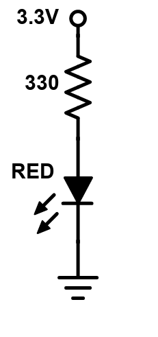 Power LED circuit diagram
Note that the long leg of the LED is the side that connects to the more positive voltage.
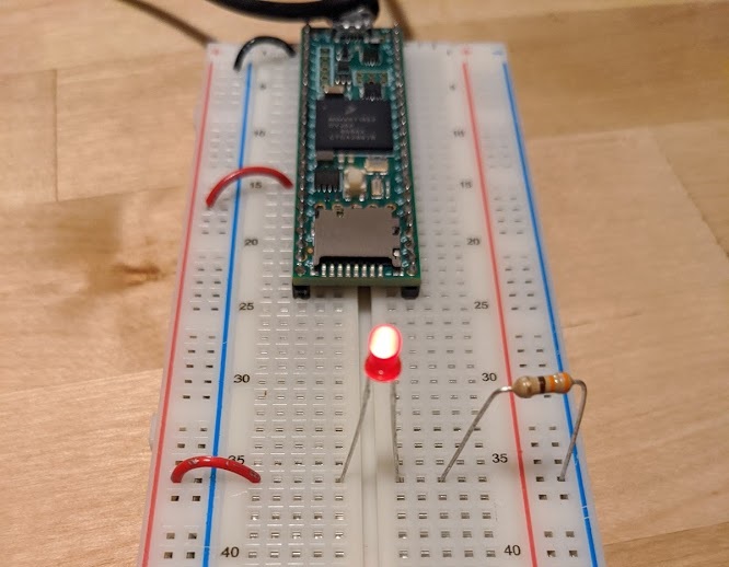
There are infinite ways to build this circuit on the breadboard. Each way will work just as well, it is all up to you! The diagram says that the long leg of the LED must touch 3.3V. The short end of the LED must touch the resistor, and the other leg of the resistor must touch ground. The touching points cannot touch other voltages. One way to build this circuit is to take a red wire from the 3.3V rail and place it in a row, place the long leg of the LED in that row and the short end in a different row. Then the resistor would go in that row to another empty row, and a black wire would connect that row to the ground rail.
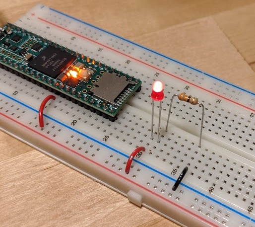 Power LED circuit
The legs of the LED and resistor are long, so you can trim them (keep the positive leg of the LED longer!) or bend them, in which case you might not need to use any wire!
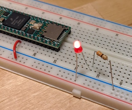 Power LED circuit
All of these circuits would work:
 Power LED circuit
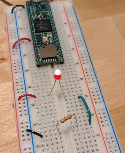 Power LED circuit
Double check your work, then plug in the USB cable, and the LED should light. If it does not, check the orientation of the LED, and make sure there are no shorts.
Use a button to turn on LED
The push button in your kit is a spring loaded conductor that conducts when the button is pressed, and disconnects when it is not pressed.
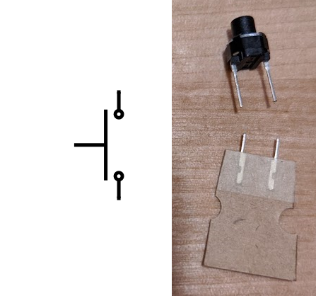 Pushbutton
This particular brand of button has funny feet that get stuck in the breadboard holes, so be sure to cut them off.
Build the following circuit with a green LED, 330ohm resistor, and push button:
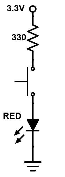 Pushbutton circuit diagram
After you cut the feet off the button it is no longer as easy to build the circuit without using any wire.
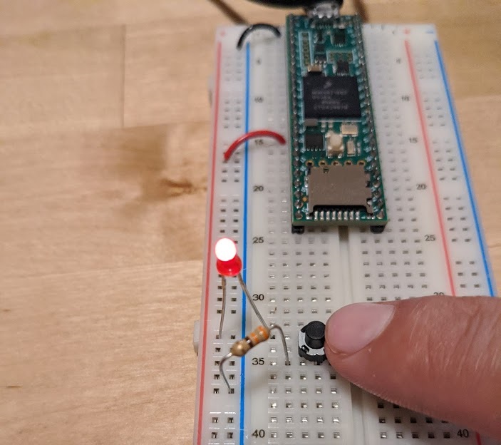 Pushbutton circuit
Press the button and the LED should light! If it doesn’t, carefully examine your circuit. Does it have connections to 3.3V and 0V? Does the long end of the LED touch the higher voltage? Are the connections made in the rows of the breadboard?
Use potentiometer to set LED brightness
The LED brightness is proportional to the current that goes through it. If we use a bigger resistor, the LED will be dimmer. If we use no resistor, the current would be extremely large and the LED might burn out! You can build a dimming LED by using a variable resistor, called a potentiometer (also just called a pot).
The pot has 3 legs:
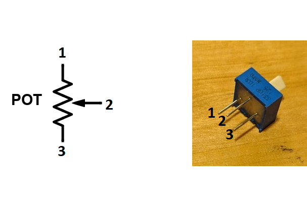 Potentiometer
In this case you only need 2 legs. Leave the third leg unconnected.
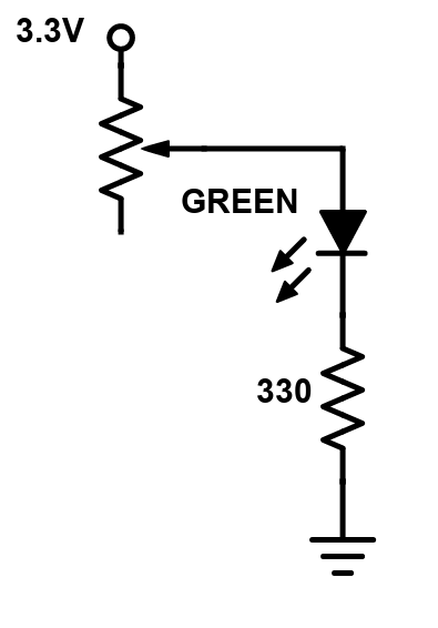 Potentiometer circuit diagram
The 330ohm resistor is used to make sure the LED has at least some resistance to prevent a short. The potentiometer has a value of 0ohm to 10kOhm, linearly proportional to the angle of the knob. Build the circuit (note that one leg of the pot is not used for anything), turn the knob, and the LED should be dim!
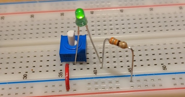 Potentiometer LED dimming circuit
CircuitPython code on the ItsyBitsy
We can build circuits all day long, using sensors like the potentiometer to control outputs like the brightness of an LED, but changing the functionality of the circuit often takes a lot of redesign and building. Instead, we can use code on a microcontroller, wired to simple circuits, to accomplish our objectives, and make it easy to change the functionality on the fly and prototype rapidly.
Installations
You may have noticed that when you plug the ItsyBitsy into your computer a memory drive, like a thumb drive, is created. There are files on the drive that contain the Python code that runs on the ItsyBitsy. To change the program, all you need to do is open code.py in a text editor and make changes, then when you save the code it starts to run!
So technically you don't need any special IDE program to write code for the ItsyBitsy, just a text editor. But Mu has some nice extra features, like a window for Repl and a plotter, so we'll use Mu again, which you should already have installed from https://codewith.mu/en/.
Open Mu and see what is already there
The ItsyBitsy comes with a program installed that runs through some of the cool things that it can do. Open Mu, change the Mode to Adafruit CircuitPython, and Open the code.py file from the CircuitPython drive.
That's a lot of code! We'll break it down over the next few exercises.
Blink the LED
There is already an LED soldered onto the ItsyBitsy on pin 13. Let's mke it blink!
The top of the code includes the libraries necessary to control the pin:
import board
import time
import gc
from digitalio import DigitalInOut, Direction, Pull
Then we can define a variable called led that represents pin 13, and make it an output:
led = DigitalInOut(board.D13)
led.direction = Direction.OUTPUT
Then in an infinite while loop we can blink the LED forever
while True:
  led.value = 1
  time.sleep(0.5)
  led.value = 0
  time.sleep(0.5)
Delete the contents of code.py and write some code that makes the LED blink once per second. When you save the code, verify that the LED blinks. Then change it so that it blinks 10 times per second. How long should each delay be? At what rate can you no longer tell that the LED is blinking, it just looks like it is always on?
Debugging with Repl
Do not expect your code to work the first time. To debug, you can enter Repl mode and see what the errors are.
To get into Repl mode, press the Serial button, then press Ctrl-c, and then press any key.
To get out of Repl mode, press Ctrl-d, and your code will start running again.
Buttons and LEDs
Edit the code so that the ItsyBitsy can read a button and control an LED. When the button is pressed, the LED should be on, and when the button is not pressed, the LED should be off. Here is the circuit diagram for the LED and button, using pins 9 and 7.
 The ItsyBitsy button and LED circuit diagram
Note that the button circuit is a little weird. What voltage does the ItsyBitsy read when the button is pressed? When the button is not pressed?
Build an LED circuit, turn on when button is pressed
You'll need to make sure the button pin is an input:
but = DigitalInOut(board.D7)
but.direction = Direction.INPUT
And you can read the value of the button like:
if(but.value==0):
    # do something
Analog Input and Output
Sensors like buttons produce only two states, which is convenient for the digital pins on the ItsyBitsy, but there are plenty of examples of sensors that produce voltages proportional to signals that cannot be read digitally. For example, the potentiometer can be wired to produce a voltage proportional to the angle of the knob. Microcontrollers, including the ItsyBitsy, have an analog to digital converter (ADC), to read the voltage and turn it into a digital number.
Visualizing Analog Voltages
The potentiometer is a knob that can be used as an angle sensor, using the following circuit diagram:
 The pot circuit diagram
The potentiometer in the kit rotates 270 degrees, and the output voltage is linearly proportional to the angle (there are also logarithmic potentiometers, used as volume knobs). The output voltage can be read by any of the A pins on the ItsyBitsy. The number returned is an integer from 0 (0V) to 65535 (3.3V).
Add the analog input library:
from analogio import AnalogIn
Make a variable to read the voltage:
analog1in = AnalogIn(board.A1)
Read the voltage into a variable
a = analog1in.value # will be 0 to 65535
Read the voltage value every 0.05 seconds and print to the computer. Can you see the column of text using the Serial button?
Edit the code so that the numbers are printed inside of parenthesis, something like:
print("("+str(analog1in.value)+")")
Try opening the Plotter, and because the number is formatted inside (), the data is plotted.
Set the brightness of the LED based on the potentiometer
Most microcontrollers don’t have the ability to generate analog voltages (using an internal digital to analog converter)((the ItsyBitsy does have a DAC, but we won’t use it for this purpose)). Instead, the microcontroller can digitally pulse a pin at high frequency so that the average value is an analog signal. The function that does this is called PWM. The amount that the pin is on is called the duty cycle, and on the ItsyBitsy ranges from 0 (off) to 65535 (full on).
Add the PWM library:
import pulseio
Replace the led variable with a pulseio variable:
led = pulseio.PWMOut(board.D9, frequency=5000, duty_cycle=0)
Set the duty cycle to some number
led.duty_cycle = #0 to 65535
RC Servo
A servo motor is a generic term for a motor that has an integrated driver and controller. Servos are used in all kinds of motion control. An RC servo is a small motor used in remote control cars, planes and boats, and is easy to control using a microcontroller. The Teensy can command the RC servo to move to any angle from 0 to 180 degrees, and the servo will hold that angle as best as it can. Servos come in many sizes and qualities, and are often highly geared to have lots of torque. The downside of the gears is audible noise when moving. Most servos use a potentiometer as a position sensor, and this limits their motion to 180 degrees. The output shaft of the servo attaches to a part called the servo horn, which can be tricky to attach to. Try not to glue directly to it (the plastic is too inert for anything to stick well), instead use a stiff wire as a pushrod.
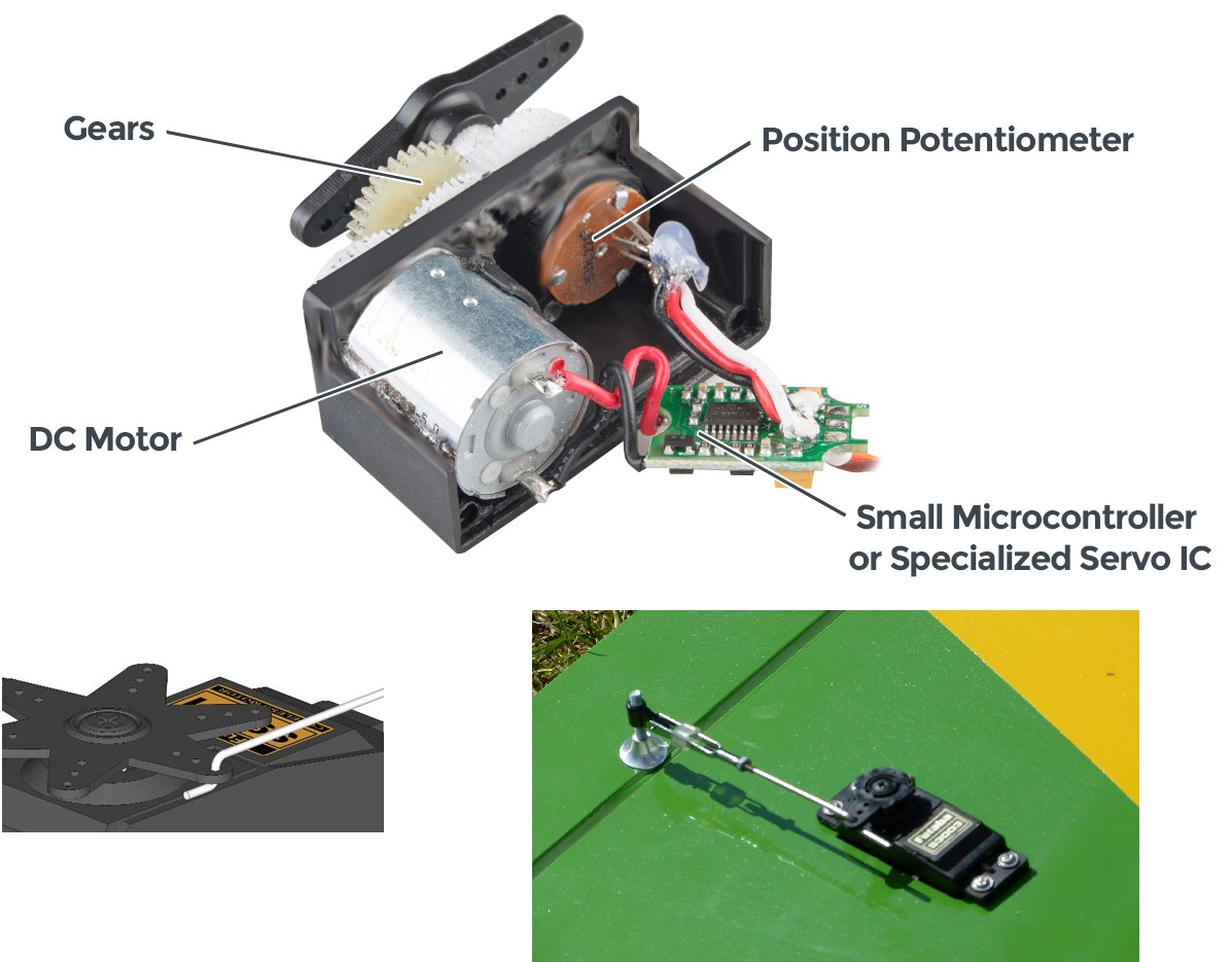 The RC servo
Wire up the RC servo, run the sweep example
The RC servo has 3 wires: brown for ground, red for 5V, and orange for signal. You can find 5V from the ItsyBitsy on pin USB. Some larger servos can use more current than the USB cable can provide, and would need an external power source from a wall adapter or a battery pack. The kit contains a set of 3 extra long header pins so you can plug the servo into the breadboard.
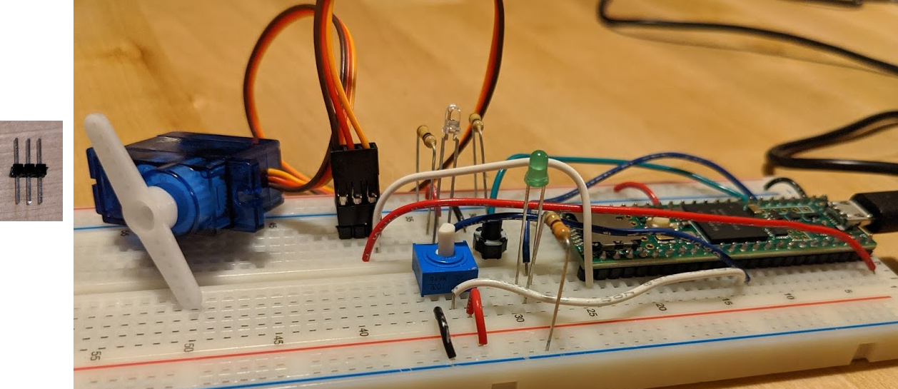 How to plug the RC servo into the breadboard
The servo is commanded using the PWM, like how pulseio pins work.
To use the servo variable type, you need to add a library to the ItsyBitsy. Download the 4.0 bundle of Adafruit code from https://github.com/adafruit/Adafruit_CircuitPython_Bundle/releases/download/20200704/adafruit-circuitpython-bundle-4.x-mpy-20200704.zip. Unzip the file, and copy the folder adafruit_motor into the lib folder on the CircuitPython drive.
You'll need the pulseio and servo libraries:
import pulseio
from adafruit_motor import servo
And you need to define a pulseio and servo object:
pwm = pulseio.PWMOut(board.D11, duty_cycle=2 ** 15, frequency=50)
my_servo = servo.Servo(pwm)
Make the servo motion mirror the potentiometer
Edit the code so that at 10Hz the potentiometer angle is read and sent to the servo, so that the servo angle matches the potentiometer angle.
Neopixel
We can set the brightness of a single color of LED using the pulseio function. How can we control a full color RGB LED, or a lot of LEDs, without using all the pins of the ItsyBitsy? A Neopixel is a brand of WS2812B RGB LEDs that can be controlled with a single pin, and chained so that a whole strip can be controlled individually for brightness and color, still using just one pin. Neopixels can be purchased individually, on long strands, and in all kinds of arrays of shapes.
Wire the Neopixel
The Neopixel board in the kit takes 5V, ground, and any pin for DIN. The other end of the board has pads to solder connections to the next set of Neopixels, connecting DOUT to the next DIN. I have pre-soldered header pins on so you can plug the board into your breadboard.
Run the example code
The Neopixels need a library called neopixel.mpy and adafruit_pypixelbuf.mpy from the Adafruit library bundle, place them in the lib folder of the CircuitPython drive.
Add the library and object
import neopixel
pixel_pin = board.D5
num_pixels = 8
pixels = neopixel.NeoPixel(pixel_pin, num_pixels, brightness=0.3, auto_write=False)
Some cool color functions:
def wheel(pos):
    # Input a value 0 to 255 to get a color value.
    # The colours are a transition r - g - b - back to r.
    if pos < 0 or pos > 255:
        return (0, 0, 0)
    if pos < 85:
        return (255 - pos * 3, pos * 3, 0)
    if pos < 170:
        pos -= 85
        return (0, 255 - pos * 3, pos * 3)
    pos -= 170
    return (pos * 3, 0, 255 - pos * 3)

def rainbow_cycle(wait):
    for j in range(255):
        for i in range(num_pixels):
            rc_index = (i * 256 // num_pixels) + j
            pixels[i] = wheel(rc_index & 255)
        pixels.show()
        time.sleep(wait)
And call the function:
rainbow_cycle(0) # Increase the number to slow down the rainbow
The Neopixels can be harshly bright, so I like to put something over them to diffuse the color, like a sheet of white paper, tissue, or cotton.
Accelerometer
An accelerometer is a MEMS device that reads the acceleration of a device. It can be used to measure motion, like step count, or which way is down, for screen orientation. Most accelerometers use digital communication like serial called I2C or SPI to relate their data. The accelerometer in the kit is from Adafruit.
To use the accelerometer you need to add a library to the ItsyBitsy. Instructions
Connect the accelerometer
The accelerometer needs 4 connections: 3.3V to VDD, ground to VSS, and the data pins, SDA to the ItsyBitsy SDA and SCL to the ItsyBitys SCL.
Plot the data
The values returned for acceleration range from -32000 to +32000, where +16000 is 1g of acceleration. -16000 is -1g, or completely downwards.
Example code
 Accelerometer data in the plotter
Solution
Set the brightness of the Neopixels to the data
Adjust the code so that if the accelerometer is tapped in the X direction, the Neopixel strip lights up green. If tapped in Y, Red, and tapped in Z, blue.
Solution
Sound
The ItsyBitsy can play high quality sound out of the DAC pin. It takes a few parts to make sound: a .wav sound file, an audio amplifier, and a speaker.
Get a file on the ItsyBitsy
Record or find some .wav file audio clips. A nice source is the free website. Copy the files to the ItsyBitsy drive, the files must be small.
Wire up the audio amplifier and speaker
The speaker requires an amplifier to produce loud and clear sound. Connect the amplifier ground to ground, 5V to 5V, VIN to DAC. I have pre-plugged the wires from the speaker into the amplifier.
 Speaker circuit
Play the sound
Example code
Play the sound and use potentiometer volume
Write some code that plays a sound when the accelerometer is tapped, the sound is played.
Solution
Solutions
Original code
# Itsy Bitsy M0 Express IO demo
# Welcome to CircuitPython 4 :)

import board
import time
import gc
from digitalio import DigitalInOut, Direction, Pull
import touchio
import pulseio
import neopixel
import adafruit_dotstar
from adafruit_motor import servo

# Audio playback
import audioio
from analogio import AnalogIn
# Analog audio output on A0, using two audio files
audiofiles = ["rimshot.wav", "laugh.wav"]

# One pixel connected internally!
dot = adafruit_dotstar.DotStar(board.APA102_SCK, board.APA102_MOSI, 1, brightness=0.5)

# Built in red LED
led = DigitalInOut(board.D13)
led.direction = Direction.OUTPUT

# Analog input on A1
analog1in = AnalogIn(board.A1)

# Capacitive touch on A2
touch = touchio.TouchIn(board.A2)

# Digital input with pullup on D7, D9, and D10
buttons = []
for p in [board.D7, board.D9, board.D10]:
    button = DigitalInOut(p)
    button.direction = Direction.INPUT
    button.pull = Pull.UP
    buttons.append(button)

# Servo on D12
servo_pwm = pulseio.PWMOut(board.D12, frequency=50)
servo = servo.Servo(servo_pwm)

# NeoPixel strip (of 16 LEDs) connected on D5
NUMPIXELS = 16
neopixels = neopixel.NeoPixel(board.D5, NUMPIXELS, brightness=0.2, auto_write=False)


######################### HELPERS ##############################

# Helper to convert analog input to voltage
def getVoltage(pin):
    return (pin.value * 3.3) / 65536

# Helper to give us a nice color swirl
def wheel(pos):
    # Input a value 0 to 255 to get a color value.
    # The colours are a transition r - g - b - back to r.
    if (pos < 0):
        return [0, 0, 0]
    if (pos > 255):
        return [0, 0, 0]
    if (pos < 85):
        return [int(pos * 3), int(255 - (pos*3)), 0]
    elif (pos < 170):
        pos -= 85
        return [int(255 - pos*3), 0, int(pos*3)]
    else:
        pos -= 170
        return [0, int(pos*3), int(255 - pos*3)]

def play_file(filename):
    print("")
    print("----------------------------------")
    print("playing file "+filename)
    with open(filename, "rb") as f:
        with audioio.WaveFile(f) as wave:
            with audioio.AudioOut(board.A0) as a:
                a.play(wave)
                while a.playing:
                    pass
    print("finished")
    print("----------------------------------")

######################### MAIN LOOP ##############################

i = 0
while True:
  # spin internal LED around! autoshow is on
  dot[0] = wheel(i & 255)

  # also make the neopixels swirl around
  for p in range(NUMPIXELS):
      idx = int ((p * 256 / NUMPIXELS) + i)
      neopixels[p] = wheel(idx & 255)
  neopixels.show()

  # Read analog voltage on A1
  print("A1: %0.2f" % getVoltage(analog1in), end="\t")

  # use A2 as capacitive touch to turn on internal LED
  print("A2 touch: %d" % touch.raw_value, end="\t")
  if touch.value:
      print("A2 touched!", end ="\t")
  led.value = touch.value

  if not buttons[1].value:
      print("Button D9 pressed!", end ="\t")
      play_file(audiofiles[0])

  if not buttons[2].value:
      print("Button D10 pressed!", end ="\t")
      play_file(audiofiles[1])

  # sweep a servo from 0-180 degrees (map from 0-255)
  servo.angle = i / 255 * 180

  i = (i+1) % 256  # run from 0 to 255
  #time.sleep(0.01) # make bigger to slow down

  print("")
Blink
import board
import time
import gc
from digitalio import DigitalInOut, Direction, Pull

led = DigitalInOut(board.D13)
led.direction = Direction.OUTPUT

while True:
    led.value = 1
    time.sleep(0.5)
    led.value = 0
    time.sleep(0.5)
Button and LED
import board
import time
import gc
from digitalio import DigitalInOut, Direction, Pull

led = DigitalInOut(board.D9)
led.direction = Direction.OUTPUT
but= DigitalInOut(board.D7)
but.direction = Direction.INPUT

while True:
    if (but.value == 0):
        led.value = 1
    else:
        led.value = 0
Pot LED Dimmer
import board
import time
import gc
from digitalio import DigitalInOut, Direction, Pull
from analogio import AnalogIn
import pulseio

led = pulseio.PWMOut(board.D9, frequency=5000, duty_cycle=0)
but= DigitalInOut(board.D7)
but.direction = Direction.INPUT
analog1in = AnalogIn(board.A1)

while True:
    led.duty_cycle = analog1in.value
Sweep
import board
import time
import gc
from digitalio import DigitalInOut, Direction, Pull
from analogio import AnalogIn

import pulseio
from adafruit_motor import servo

led = pulseio.PWMOut(board.D9, frequency=5000, duty_cycle=0)
but= DigitalInOut(board.D7)
but.direction = Direction.INPUT
analog1in = AnalogIn(board.A1)

# create a PWMOut object on Pin A2.
pwm = pulseio.PWMOut(board.D11, duty_cycle=2 ** 15, frequency=50)
my_servo = servo.Servo(pwm)

while True:
    print("("+str(analog1in.value)+")")
    time.sleep(0.05)

    for angle in range(0, 180, 5):  # 0 - 180 degrees, 5 degrees at a time.
        my_servo.angle = angle
        time.sleep(0.05)
    for angle in range(180, 0, -5): # 180 - 0 degrees, 5 degrees at a time.
        my_servo.angle = angle
        time.sleep(0.05)
Servo Potentiometer
import board
import time
import gc
from digitalio import DigitalInOut, Direction, Pull
from analogio import AnalogIn

import pulseio
from adafruit_motor import servo

led = pulseio.PWMOut(board.D9, frequency=5000, duty_cycle=0)
but= DigitalInOut(board.D7)
but.direction = Direction.INPUT
analog1in = AnalogIn(board.A1)

# create a PWMOut object on Pin A2.
pwm = pulseio.PWMOut(board.D11, duty_cycle=2 ** 15, frequency=50)
my_servo = servo.Servo(pwm)

while True:
    print("("+str(analog1in.value)+")")
    time.sleep(0.05)
    my_servo.angle = analog1in.value * 180 / 65535
Neopixels
import board
import time
import gc

import neopixel

def wheel(pos):
    # Input a value 0 to 255 to get a color value.
    # The colours are a transition r - g - b - back to r.
    if pos < 0 or pos > 255:
        return (0, 0, 0)
    if pos < 85:
        return (255 - pos * 3, pos * 3, 0)
    if pos < 170:
        pos -= 85
        return (0, 255 - pos * 3, pos * 3)
    pos -= 170
    return (pos * 3, 0, 255 - pos * 3)

def rainbow_cycle(wait):
    for j in range(255):
        for i in range(num_pixels):
            rc_index = (i * 256 // num_pixels) + j
            pixels[i] = wheel(rc_index & 255)
        pixels.show()
        time.sleep(wait)

pixel_pin = board.D5
num_pixels = 8
pixels = neopixel.NeoPixel(pixel_pin, num_pixels, brightness=0.3, auto_write=False)

while True:
    rainbow_cycle(0)  # Increase the number to slow down the rainbow
Appendix
What you may have missed by using just the lab kit
Your lab kit just scratches the surface of possible parts that can be used with the Teensy. There are also lots of tools that can be helpful for design and debugging that could not be included for price and size reasons.
The Mechatronics Design Lab at Northwestern University has 8 lab benches with variable power supplies, oscilloscopes, function generators, benchtop multimeters, and more. When it is safe to do so, please stop by to check it out.
Soldering
A good mechatronics bootcamp should include the opportunity to solder some components. When you have prototyped a circuit and are ready to move to a more permanent device, the breadboard can be replaced by a solder-able protoboard or a custom designed printed circuit board. These require the components to be soldered to be reliable.
Soldering is the act of welding electrical components with solder for the purposes of electrical conductivity (there is also a version of soldering to make a mechanical joint, like in a pipe, electrical soldering is much lower energy process). Soldering uses a 30W iron in the shape of a pencil (not a gun or torch, those have other uses). To solder, mate the two conductors, heat them to the melting temperature of solder using the iron, and apply solder. Soldering is all about heat transfer: if the conductors are not hot enough, the solder will not melt and wick into the joint. To aid in transferring heat from the iron to the conductors, solder is applied to the tip of the iron because the liquid solder bubble transfers heat more effectively than dry metal-to-metal contact. The solder bubble does not leave the iron tip, it is only there to help with heat transfer! Solder is not applied like glue in that way.
When you get a chance to try it out, try:
- Solder two wires together
- Solder the strands of a stranded wire into a solid wire
- Solder a resistor into a solder-able protoboard
- Remove a component from protoboard and suck out the solder
- Solder header pins into a breakout board
3d printing and Laser cutting
Most projects will need some mechanical parts and an enclosure to house the electronics. There are lots of pre-made boxes available, but with a little time invested in learning computer aided design (CAD) you can model custom parts and use rapid prototyping tools to create them. It is tempting to 3d print everything, but laser cutting is usually faster and more effective, especially for parts that are mostly made of flat surfaces. Don’t let me catch you printing a box! Those should be made with the laser cutter.
PCB design
A printed circuit board can be manufactured and delivered in as little as a week for under $50. It makes a prototype much more reliable and professional looking. Check out these tutorials for using Eagle CAD to draw a PCB.
Links
- Arduino code reference
- Teensy website
- General C help
Where to find parts
There are many websites that sell “breakout boards” for components that cannot be plugged into a breadboard. Before you buy, make sure the vendor has some sample code available.
-
Sparkfun Sells a nice array of Arduino and Raspberry Pi compatible parts
-
Adafruit Has very nice tutorials for all of their parts, strongly supports Circuit Python (using python to program the microcontroller instead of C)
-
Pololu Has nice sensor boards and high quality motors and motor drivers
-
Servo City Lots of different sizes of servos and servo attachments
-
Seeed Like Sparkfun and Adafruit, but pay attention to the shipping times
-
Hobbyking More powerful motors and moor drivers, lot of random parts, make sure to ship from a US warehouse
-
Digikey / Mouser / Newark Sources for low level components and an alternate supplier for the above vendors
-
Amazon Lots of stuff here but sometimes a low price is a knockoff part, also pay attention to weird shipping times
-
Aliexpress The best source for parts in higher quantities, but expect expensive or long shipping times